The block diagram of a cascade system used to control water level in a steam generator of
Question:
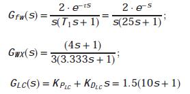
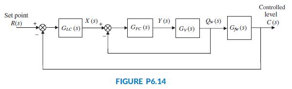
The block diagram of a cascade system used to control water level in a steam generator of a nuclear power plant (Wang, 2009) was presented in FigureP6.14. In that system, the level controller, GLC(s), is the master controller and the feed-water flow controller, GFC(s), is the slave controller. Consider that the inner feedback loop is replaced by its equivalent transfer function, GWX(s). Using numerical values in (Wang, 2009) and (Bhambhani, 2008) the transfer functions with a 1 second pure delay are:
Use MATLAB or any other program to:
a. Obtain Bode magnitude and phase plots for this system using a fifth-order Padé approximation (available in MATLAB). Note on these plots, if applicable, the gain and phase margins.
b. Plot the response of the system, c(t), to a unit step input, r(t) = u(t). Note on the c(t) curve the rise time, Tr, the settling time, Ts, the final value of the output, and, if applicable, the percent overshoot, %OS, and mid peak time, Tp.
c. Repeat the above two steps for a pure delay of 1.5 seconds.
Step by Step Answer:

This question has not been answered yet.
You can Ask your question!