

Question: The prefix network shown in Figure 5.7 uses black cells to compute all of the prefixes. Some of the block propagate signals are not actually
The prefix network shown in Figure 5.7 uses black cells to compute all of the prefixes. Some of the block propagate signals are not actually necessary. Design a “gray cell” that receives G and P signals for bits i:k and k−1:j but produces only Gi:j, not Pi:j. Redraw the prefix network, replacing black cells with gray cells wherever possible.
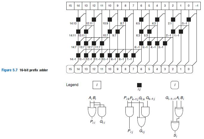
14 13 12 11 10 9 8 1 0 15 7 5 3 2 -1 14:13 12:11 10:9 8:7 6:5 4:3 2:1 0:-1 14:11 13:11 10:7 9:7 6:3 5:3 2:-1 1:-1 14:7 13:7 12:7 11:7 6:-1 5:-1 4:-1 3:-1 14:-1 13:-1 12:-1 11:-1 10:-1 9:-1 8:-1 |7:-1 15 14 13 12 11 10 9 7 6 Figure 5.7 16-bit prefix adder Legend i:j A; B; G-1-1A; B; Pii G Pii S; 4,
Step by Step Solution
3.42 Rating (168 Votes )
There are 3 Steps involved in it
15 14 13 12 11 1413 1411 1311 15 1211 147 137 127 117 14 ... View full answer

Get step-by-step solutions from verified subject matter experts