

Question: Realize the SM chart of Problem 5.16 using the two-address microprogramming structure shown in Figure 5-29. (a) Convert the SM chart to the proper form
Realize the SM chart of Problem 5.16 using the two-address microprogramming structure shown in Figure 5-29.
(a) Convert the SM chart to the proper form by adding a minimum number of states to the given chart.
(b) Write the microprogram required to implement the circuit.
(c) What is the size of the ROM required for microprogramming?
(d) What is the size of the ROM if no microprogram is used but the traditional ROM method is used to implement the original SM chart?
Data from Problem 5.16.
Realize the following SM chart using a ROM with a minimum number of inputs, a multiplexer, and a loadable counter (like the 74163). The ROM should generate NST. The multiplexer inputs are selected as shown in the table beside the SM chart.
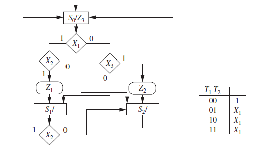
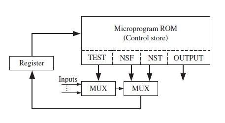
Figure 5-29: Typical Hardware Arrangement for Microprogramming
SJZ3 X1 (X2 X3 Z2 T, T, 00 S,/ X1 X1 01 10 11 X2 'x
Step by Step Solution
3.46 Rating (162 Votes )
There are 3 Steps involved in it
a b c 7 11 or 8 11 d 2 ... View full answer

Get step-by-step solutions from verified subject matter experts