

Question: Realize the SM chart of Problem 5.20 using the two-address microprogramming hardware structure shown in Figure 5-29. (a) Convert the SM chart to the proper
Realize the SM chart of Problem 5.20 using the two-address microprogramming hardware structure shown in Figure 5-29.
(a) Convert the SM chart to the proper form by adding a minimum number of states to the given diagram. What are the changes needed?
(b) Write the microcode for implementing this state machine using the indicated hardware. You may indicate states in the microcode using the state names S0, S1, and so forth instead of using a bit assignment. Indicate the MUX connections (inputs) necessary to understand your microcode.
(c) What is the size of the microcode ROM? Explain your calculation.
(d) If the given (original) SM chart is implemented using a traditional ROM method, how big a ROM is needed? Explain your calculation.
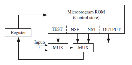 Figure 5-29: Typical Hardware Arrangement for Microprogramming
Microprogram ROM (Control store) TEST NSF NST OUTPUT Register Inputs MUX MUX
Step by Step Solution
3.39 Rating (171 Votes )
There are 3 Steps involved in it
a 1 Convert Mealy outputs to Moore outputs 2 Only one input tested per state b Test ... View full answer

Get step-by-step solutions from verified subject matter experts