

Question: Design a logic circuit that has two signal inputs, A 1 and A 0 , and a control input S so that it functions according
Design a logic circuit that has two signal inputs, A1 and A0, and a control input S so that it functions according to the requirements given in Figure 4-78. (This type of circuit is called a multiplexer and will be covered in Chapter 9.)
Figure 4-78
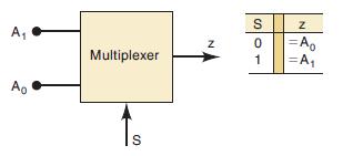
A Ao Multiplexer S Z S01 S N |=A =A
Step by Step Solution
★★★★★
3.42 Rating (155 Votes )
There are 3 Steps involved in it
1 Expert Approved Answer
Step: 1 Unlock

Question Has Been Solved by an Expert!
Get step-by-step solutions from verified subject matter experts
Step: 2 Unlock
Step: 3 Unlock