

Question: Develop a procedure for isolating the fault that is causing the malfunction described in Problem 4-44. Data from Problem 4-44 Refer to the logic circuit
Develop a procedure for isolating the fault that is causing the malfunction described in Problem 4-44.
Data from Problem 4-44
Refer to the logic circuit of Figure 4-41. Recall that output Y is supposed to be HIGH for either of the following conditions:
1. A = 1, B = 0, regardless of C
2. A = 0, B = 1, C = 1
When testing the circuit, the technician observes that Y goes HIGH only for the first condition but stays LOW for all other input conditions.
Consider the following list of possible faults. For each one, write yes or no to indicate whether or not it could be the actual fault. Explain your reasoning for each no response.
(a) An internal short to ground at Z2-13
(b) An open circuit in the connection to Z2-13
(c) An internal short to VCC at Z2-11
(d) An open circuit in the VCC connection to Z2
(e) An internal open circuit at Z2-9
(f) An open in the connection from Z2-11 to Z2-9
(g) A solder bridge between pins 6 and 7 of Z2
Figure 4-41
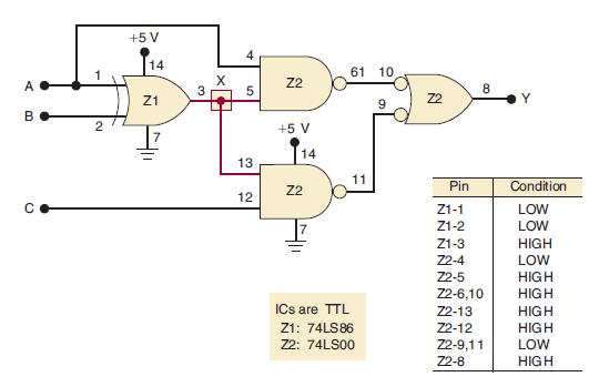
A B 2 +5 V 14 Z1 X 5 13 12 Z2 +5 V 14 Z2 61 10 11 ICs are TTL Z1: 74LS86 Z2: 74LS00 9 Z2 Pin Z1-1 Z1-2 Z1-3 Z2-4 Z2-5 8 Z2-6,10 Z2-13 Z2-12 Z2-9,11 Z2-8 Condition LOW LOW HIGH LOW HIGH HIGH HIGH HIGH LOW HIGH
Step by Step Solution
3.42 Rating (152 Votes )
There are 3 Steps involved in it

Get step-by-step solutions from verified subject matter experts