

Figure 5-65 shows a three-bit shift register made up of TTL flip-flops. Initially, all of the FFs
Question:
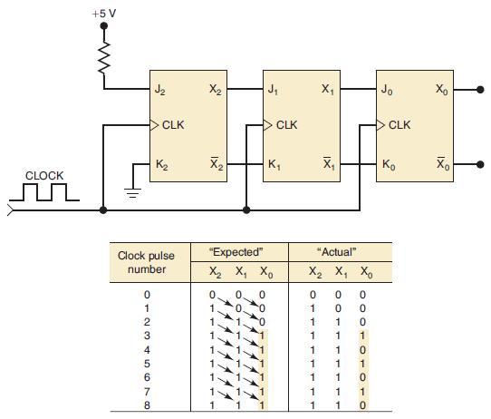
Figure 5-65 shows a three-bit shift register made up of TTL flip-flops. Initially, all of the FFs are in the LOW state before clock pulses are applied. As clock pulses are applied, each PGT will cause the information to shift from each FF to the one on its right. The diagram shows the “expected” sequence of FF states after each clock pulse. Since J2 = 1 and K2 = 0, flipflop X2 will go HIGH on clock pulse 1 and will stay there for all subsequent pulses. This HIGH will shift into X1, and then X0 on clock pulses 2 and 3, respectively. Thus, after the third pulse, all FFs will be HIGH and should remain there as pulses are continually applied.
Now let’s suppose that the “actual” response of the FF states is as shown in the diagram. Here the FFs change as expected for the first three clock pulses. From then on, flip-flop X0, instead of staying HIGH, alternates between HIGH and LOW. What possible circuit fault can produce this operation?
Figure 5-65
Step by Step Answer:
On the second pulse FF X 1 goes HIGH This should make J 0 1 K 0 0 so that all subsequent clo...View the full answer


Digital Systems Principles And Application
ISBN: 9780134220130
12th Edition
Authors: Ronald Tocci, Neal Widmer, Gregory Moss
