

Figure 9-4(a) shows how four 74ALS138s and an INVERTER can be arranged to function as a 1-of-32
Question:
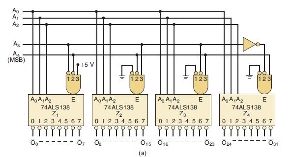
Figure 9-4(a) shows how four 74ALS138s and an INVERTER can be arranged to function as a 1-of-32 decoder. The decoders are labeled Z1 to Z4 for easy reference, and the eight outputs from each one are combined into 32 outputs. Z1’s outputs are O̅0 to O̅7; Z2’s outputs O̅0 to O̅7 are renamed O̅8 to O̅15, respectively; Z3’s outputs are renamed O̅16 to O̅23; and Z4’s are renamed O̅24 to O̅31. A five-bit input code A4A3A2A1A0 will activate only one of these 32 outputs for each of the 32 possible input codes.
(a) Which output will be activated for A4A3A2A1A0 = 01101?
(b) What range of input codes will activate the Z4 chip?
(c) Create a megafunction circuit in Quartus that will implement a 1-of-32 decoder with active-HIGH outputs.
Figure 9-4(a)
Step by Step Answer:
a The fivebit code has two distinct portions The A 4 and A 3 bits determine which one of the ...View the full answer


Digital Systems Principles And Application
ISBN: 9780134220130
12th Edition
Authors: Ronald Tocci, Neal Widmer, Gregory Moss
