

Question: Modify (a) The AHDL design in Figure 4-63 to implement Table 4-1. (b) The VHDL design in Figure 4-64 to implement Table 4-1. Figure 4-63
Modify
(a) The AHDL design in Figure 4-63 to implement Table 4-1.
(b) The VHDL design in Figure 4-64 to implement Table 4-1.
Figure 4-63
![SUBDESIGN Figure 4-63 ( ) P, q, r S VARIABLE status [2..0] BEGIN END CASE; : INPUT; :OUTPUT; END; :NODE;](https://dsd5zvtm8ll6.cloudfront.net/images/question_images/1699/6/8/7/564654f2c8c0ec641699687563891.jpg)
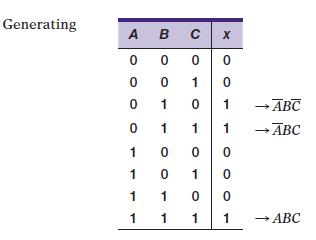
Table 4-1
SUBDESIGN Figure 4-63 ( ) P, q, r S VARIABLE status [2..0] BEGIN END CASE; : INPUT; :OUTPUT; END; :NODE; status] (p, q, r); -- link input bits in order. CASE status [] IS WHEN b"100" WHEN b"101" WHEN b"110" WHEN OTHERS -- define inputs to block -- define outputs -> 3 - GND; ->s - GND; -> S GND; ->3- VCC;
Step by Step Solution
★★★★★
3.37 Rating (169 Votes )
There are 3 Steps involved in it
1 Expert Approved Answer
Step: 1 Unlock

Question Has Been Solved by an Expert!
Get step-by-step solutions from verified subject matter experts
Step: 2 Unlock
Step: 3 Unlock