

Modify the circuit of Figure 5-9 to use a NOR gate latch. Figure 5-9 +5 V 2
Question:
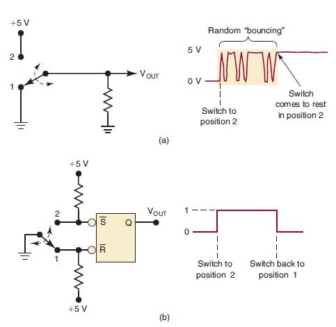
Modify the circuit of Figure 5-9 to use a NOR gate latch.
Figure 5-9
Fantastic news! We've Found the answer you've been seeking!
Step by Step Answer:

Answered By
Jacob Festus
I am a professional Statistician and Project Research writer. I am looking forward to getting mostly statistical work including data management that is analysis, data entry using all the statistical software’s such as R Gui, R Studio, SPSS, STATA, and excel. I also have excellent knowledge of research and essay writing. I have previously worked in other Freelancing sites such as Uvocorp, Essay shark, Bluecorp and finally, decided to join the solution inn team to continue with my explicit work of helping dear clients and students achieve their Academic dreams. I deliver, quality and exceptional projects on time and capable of working under high pressure.
1250+ Reviews
2838+ Question Solved
Related Book For 

Digital Systems Principles And Application
ISBN: 9780134220130
12th Edition
Authors: Ronald Tocci, Neal Widmer, Gregory Moss
Question Posted:
