

Modify the circuit of Figure 9-6 so that relay K 1 stays energized from PGT 3 to
Question:
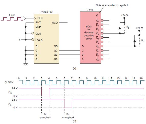
Modify the circuit of Figure 9-6 so that relay K1 stays energized from PGT 3 to 5 and K2 stays energized from PGT 6 to 9.
Figure 9-6
Fantastic news! We've Found the answer you've been seeking!
Step by Step Answer:

Answered By
Shebla K
I am an MBA graduate having experience as an Assistant Professor at University level for two years. I always prepare well for a class as I believe that only if you become an ocean you can give a bucket of water. Being a teacher was not only my profession but also my passion.
1+ Reviews
10+ Question Solved
Related Book For 

Digital Systems Principles And Application
ISBN: 9780134220130
12th Edition
Authors: Ronald Tocci, Neal Widmer, Gregory Moss
Question Posted:
