

Refer to Figure 10-44. The block on the left is simply combinational logic that must control the
Question:
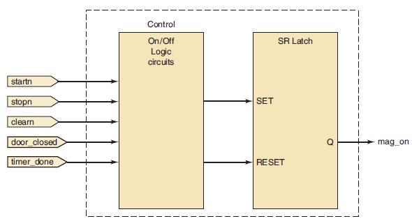
Refer to Figure 10-44. The block on the left is simply combinational logic that must control the S-R latch that turns on and off the magnetron tube.
(a) Draw a logic diagram using only gates to implement this circuit.
(b) Describe this block using AHDL.
(c) Describe this block using VHDL.
Figure 10-44
Step by Step Answer:

This question has not been answered yet.
You can Ask your question!
Related Book For 

Digital Systems Principles And Application
ISBN: 9780134220130
12th Edition
Authors: Ronald Tocci, Neal Widmer, Gregory Moss
Question Posted:
