

Refer to the IC counter circuit in Figure 7-107(a). (a) Draw the timing diagram for outputs QD
Question:
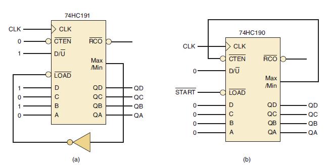
Refer to the IC counter circuit in Figure 7-107(a).
(a) Draw the timing diagram for outputs QD QC QB QA.
(b) What is the counter’s modulus?
(c) What is the count sequence? Does it count up or down?
(d) Can we produce the same modulus with a 74HC190? Can we produce the same count sequence with a 74HC190
Figure 7-107
Step by Step Answer:

This question has not been answered yet.
You can Ask your question!
Related Book For 

Digital Systems Principles And Application
ISBN: 9780134220130
12th Edition
Authors: Ronald Tocci, Neal Widmer, Gregory Moss
Question Posted:
