

Question: Repeat Problem 7-21 for the IC counter circuit in Figure 7-106(b). Data from Problem 7-21 Refer to the IC counter circuit in Figure 7-106(a): (a)
Repeat Problem 7-21 for the IC counter circuit in Figure 7-106(b).
Data from Problem 7-21
Refer to the IC counter circuit in Figure 7-106(a):
(a) Draw the state transition diagram for the counter’s QD QC QB QA outputs.
(b) Determine the counter’s modulus.
(c) What is the relationship of the output frequency of the MSB to the input CLK frequency?
(d) What is the duty cycle of the MSB output waveform?
Figure 7-106
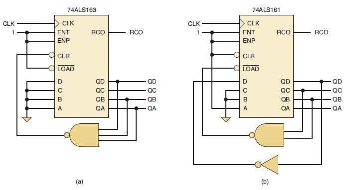
CLK 1 74ALS163 CLK ENT ENP DCBA CLR LOAD (a) RCO QC QB QA RCO QC QB -QA CLK 1 74ALS161 CLK ENT ENP CLR LOAD DCBA (b) RCO QC QB QA RCO QD QC QB QA
Step by Step Solution
3.53 Rating (153 Votes )
There are 3 Steps involved in it

Get step-by-step solutions from verified subject matter experts