

Question: Repeat Example 7-22 with DS = 1 and the input waveforms given in Figure 7-117. Figure 7-117 Data from Example 7-22 Determine the output signal
Repeat Example 7-22 with DS = 1 and the input waveforms given in Figure 7-117.
Figure 7-117
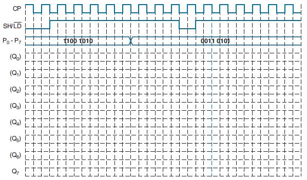
Data from Example 7-22
Determine the output signal at Q7 if we connect a 74HC165 with DS = 0 and CP INH = 0 and then apply the input waveforms given in Figure 7-72. P0 – P7 represent the parallel data on P0 P1 P2 P3 P4 P5 P6 P7.
Figure 7-72
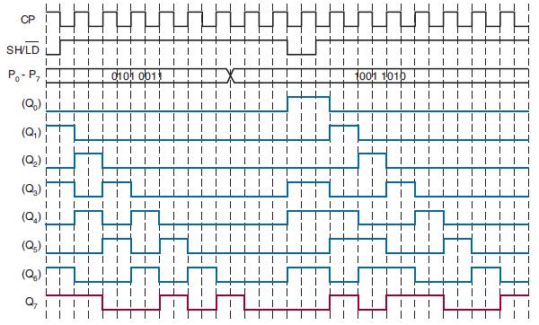
CP SH/LD Po-P7 (Q) (Q) (Q) (Q3) (Q4) (Q) TT (Q) Q7 F+ || FT LILLL 1100 1010 0011 0101 TFT 1-1 1-1 r -- -H J_L -+ ++- FH
Step by Step Solution
★★★★★
3.33 Rating (156 Votes )
There are 3 Steps involved in it
1 Expert Approved Answer
Step: 1 Unlock

Question Has Been Solved by an Expert!
Get step-by-step solutions from verified subject matter experts
Step: 2 Unlock
Step: 3 Unlock