

Repeat Problem 7-9 for the counter of Figure 7-8(a) with a 70-kHz clock. Figure 7-8(a) Data from
Question:
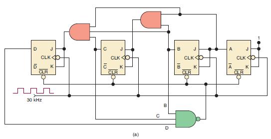
Repeat Problem 7-9 for the counter of Figure 7-8(a) with a 70-kHz clock.
Figure 7-8(a)
Data from Problem 7-9
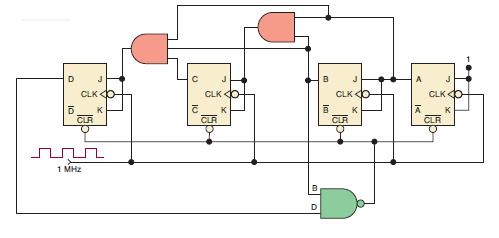
The decade counter in Figure 7-8(b) has a 1-kHz clock applied.
(a) Draw the waveforms for each FF output, showing any glitches that may occur.
(b) Determine the frequency of the signal at the D output.
(c) If the counter is originally at state 1000, what state will the counter be at after 14 clock pulses are applied?
(d) If the counter is originally at state 0101, what state will the counter be at after 20 clock pulses are applied?
Figure 7-8(b)
Step by Step Answer:

This question has not been answered yet.
You can Ask your question!
Related Book For 

Digital Systems Principles And Application
ISBN: 9780134220130
12th Edition
Authors: Ronald Tocci, Neal Widmer, Gregory Moss
Question Posted:
