

Photoelastic studies of the stress distribution around the tip of a crack have produced the isochromatic fringe
Question:
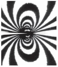
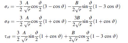
Photoelastic studies of the stress distribution around the tip of a crack have produced the isochromatic fringe pattern (opening mode I case) as shown in the figure. Using the solution given in (8.4.57), show that maximum shear stresses for each mode case are given by:
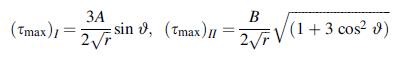
Next, plot contours of constant maximum shear stress for modes I and II. In plotting each case, normalize τ, max by the coefficient A or B. For the mode I case, theoretical contours should compare with the following photo elastic picture.
Equation 8.4.57
Fantastic news! We've Found the answer you've been seeking!
Step by Step Answer:
Mode I 0 Je Tre 32 3 A 2 T 3 A 3 A I cos3cos 9 2T 3A 25 co...View the full answer

Answered By
Antony Sang
I am a research and academic writer whose work is outstanding. I always have my customer's interests at heart. Time is an important factor in our day to day life so I am always time conscious. Plagiarism has never been my thing whatsoever. I give best Research Papers, Computer science and IT papers, Lab reports, Law, programming, Term papers, English and literature, History, Math, Accounting, Business Studies, Finance, Economics, Business Management, Chemistry, Biology, Physics, Anthropology, Sociology, Psychology, Nutrition, Creative Writing, Health Care, Nursing, and Articles.
2+ Reviews
10+ Question Solved
Related Book For 

Elasticity Theory Applications And Numerics
ISBN: 9780128159873
4th Edition
Authors: Martin H. Sadd Ph.D.
Question Posted:
