

Question: Using the information provided in Fig. 3.23 regarding PDmax, V CE max, I C max and V CE sat, sketch the boundaries of operation for
Using the information provided in Fig. 3.23 regarding PDmax, VCEmax, ICmax and VCEsat, sketch the boundaries of operation for the device.
Fig. 3.23
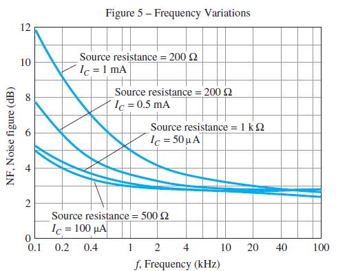

Figure 5 Frequency Variations 12 Source resistance = 200 2 Ic =1 mA 10 Source resistance = 200 2 Ic = 0.5 mA 8 Source resistance = 1 k2 Ic = 50 A Source resistance = 500 2 1.-100 !! 0.1 1 2 f, Frequency (kHz) 0.2 0.4 4 10 20 40 100 NF, Noise figure (dB) 2.
Step by Step Solution
3.24 Rating (162 Votes )
There are 3 Steps involved in it
To sketch the boundaries of operation for a transistor you need to consider the maximum ratings for ... View full answer

Get step-by-step solutions from verified subject matter experts