New Semester
Started
Get
50% OFF
Study Help!
--h --m --s
Claim Now
Question Answers
Textbooks
Find textbooks, questions and answers
Oops, something went wrong!
Change your search query and then try again
S
Books
FREE
Study Help
Expert Questions
Accounting
General Management
Mathematics
Finance
Organizational Behaviour
Law
Physics
Operating System
Management Leadership
Sociology
Programming
Marketing
Database
Computer Network
Economics
Textbooks Solutions
Accounting
Managerial Accounting
Management Leadership
Cost Accounting
Statistics
Business Law
Corporate Finance
Finance
Economics
Auditing
Tutors
Online Tutors
Find a Tutor
Hire a Tutor
Become a Tutor
AI Tutor
AI Study Planner
NEW
Sell Books
Search
Search
Sign In
Register
study help
engineering
engineering mechanics statics 15th
Engineering Mechanics Statics 15th Edition Russell C. Hibbeler - Solutions
Determine the horizontal force F required to maintain equilibrium of the slider mechanism when θ = 60°. Set M = 6 N · m D 0.5 m F 0.5 m B M 0.5 m
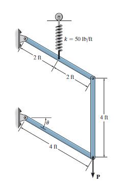
If each of the three links of the mechanism has a weight of 20 lb, determine the angle θ for equilibrium. The spring, which always remains vertical due to the roller guide, is unstretched when θ = 0°. Set P = 0. 2 fl 4 fl k = 50 lb/ft 2 ft 4 ft P
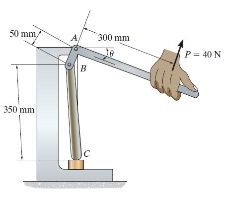
If a force P = 40 N is applied perpendicular to the handle of the toggle press, determine the vertical compressive force developed at C; θ = 30°. 50 mm 350 mm A B C 300 mm 10 P = 40 N
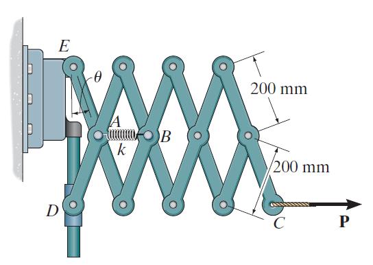
The “Nuremberg scissors” is subjected to a horizontal force of . Determine the angle θ for equilibrium. The spring has a stiffness of k = 15 kN/m and is unstretched when θ = 15°. E A mamma B 1000 k D 200 mm 200 mm C P
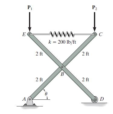
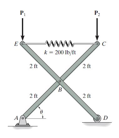
If vertical forces P1 = 40 lb and P2 = 20 lb act at C and E as shown, determine the angle θ for equilibrium. The spring is unstretched when θ = 45°. Neglect the weight of the members. E A P₁ 2 ft 2 ft wwwwwww k = 200 lb/ft B 2 ft 2 ft P₂ C D
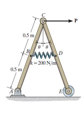
The spring has an unstretched length of 0.3 m. Determine the angle θ for equilibrium if the uniform links each have a mass of 5 kg. Set P = 0. 0.5 m 0.5 m B/ 00 www.D k=200 N/m E ►P
If vertical forces P1 = P2 = 30 lb act at C and E as shown, determine the angle θ for equilibrium. The spring is unstretched when θ = 45°. Neglect the weight of the members. E A P₁ 2 ft 2 ft wwwwww k = 200 lb/ft B 2 ft 2 ft P2 C D
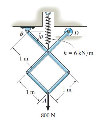
The members of the mechanism are pin connected. If a vertical force of 800 N acts at A, determine the angle θ for equilibrium. The spring is unstretched when θ = 0°. Neglect the mass of the links. B 1 m 1 m 800 N D k = 6 kN/m 1m
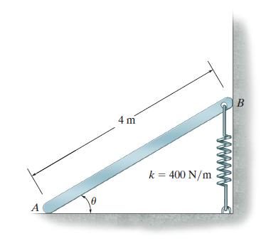
The uniform bar has a mass of 80 kg. Determine the angle θ for equilibrium and investigate the stability of the bar when it is in this position. The spring has an unstretched length when θ = 90°. A 4 m k = 400 N/m B
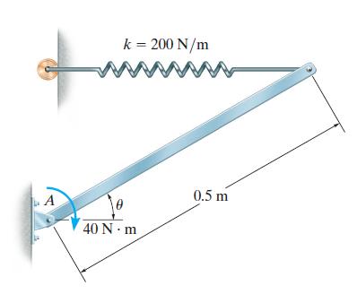
Determine the force in the spring required tokeep the 6-kg rod in equilibrium when θ = 30°. The spring remains horizontal due to the roller guide. A k = 200 N/m wwwww 40 N·m 0.5 m
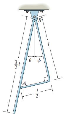
Each bar has a mass per length of m0. Determine the angles θ and Ø for equilibrium. The contact at A is smooth, and both are pin connected at B. लात A B ∙IN
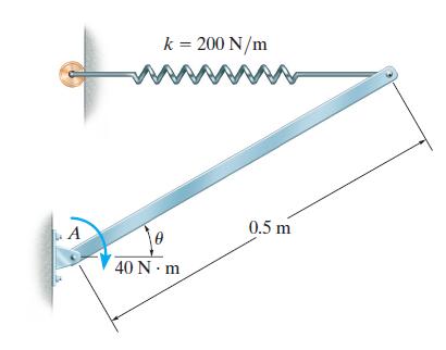
The door has a uniform weight of 50 lb. It is hinged at A and is held open by the 30-lb weight and the pulley. Determine the angle θ for equilibrium. A k = 200 N/m wwwww 0 40 N·m 0.5 m
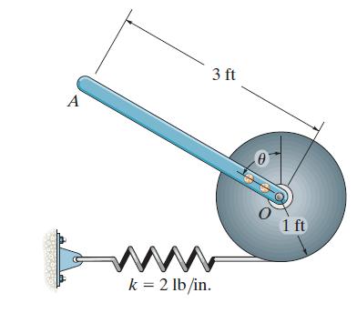
The uniform rod OA weighs 20 lb, and when the rod is in the vertical position, the spring is unstretched. Determine the position for equilibrium. Investigate the stability at the equilibrium position. A 3 ft k = 2 lb/in. 0 0 1 ft
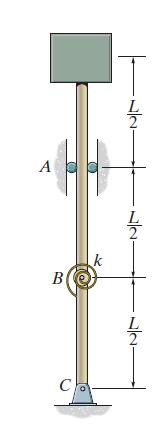
A spring with a torsional stiffness k is attached to the hinge at B. It is unstretched when the rod assembly is in the vertical position. Determine the weight W of the block that results in neutral equilibrium. Establish the potential energy function for a small angle θ, i.e., approximate sin θ
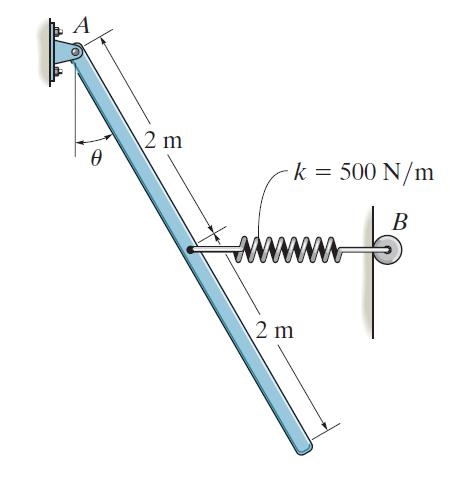
The uniform rod has a mass of 100 kg. If the spring is unstretched when θ = 60°, determine the angle θ for equilibrium and investigate the stability at the equilibrium position. The spring is always in the horizontal position due to the roller guide at B. A 0 2 m k = 500 N/m B wwwwwwww 2 m
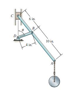
A 3-lb weight is attached to the end of rod ABC. If the rod is supported by a smooth slider block at C and rod BD, determine the angle θ for equilibrium. Neglect the weight of the rods and the slider. C D 6 in. B 4 in. 10 in. A
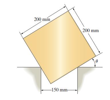
The homogeneous block has a mass of 10 kg and rests on the smooth corners of two ledges. Determine the angle θ for placement that will cause the block to be stable. 200 mm -150 mm- 200 mm
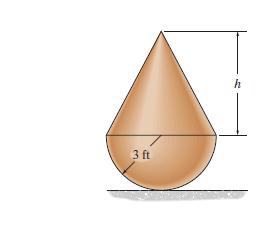
A cone is attached to the hemisphere. If both pieces have the same density, determine the height h of the cone if the configuration is to be in neutral equilibrium. 3 ft h
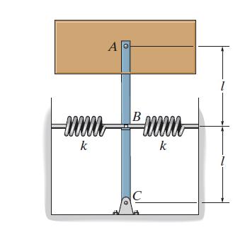
The block weighs W and is supported by links AB and BC. Determine the necessary spring stiffness k required to hold the system in neutral equilibrium. The springs are subjected to an initial compression F0 when the links are vertical as shown. mm- k A o в C XXXXX www k
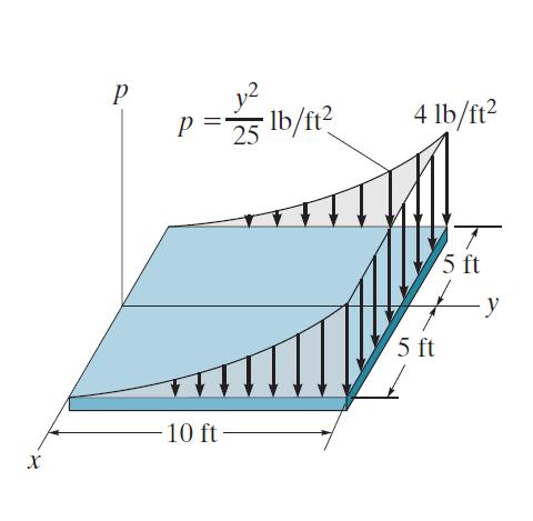
Determine the magnitude and location of the resultant force of the parabolic loading acting on the plate. X P P = 10 ft 25 lb/ft² 4 lb/ft² 5 ft 5 ft - y
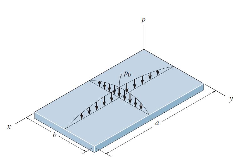
The rectangular plate is subjected to a distributed load over its entire. The load is defined by the expression where represents the p = p0 sin (πx/a) sin (πy/b), the pressure acting at the center of the plate. Determine the magnitude and location of the resultant force acting on the plate. в
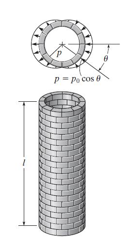
A wind loading creates a positive pressure on one side of the chimney and a negative (suction) pressure on the other side, as shown. If this pressure loading acts uniformly along the chimney’s length, determine the magnitude of the resultant force created by the wind. IT P 17 P= Po cos 0
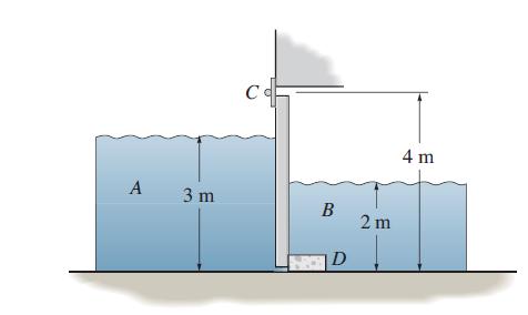
When the tide water A subsides, the tide gate automatically swings open to drain the marsh B. For the condition of high tide shown, determine the horizontal reactions developed at the hinge C and stop block D. The length of the gate is 6 m and its height is 4 m. ρw = 1.0 Mg/m3. A 3 m c Co B D 2
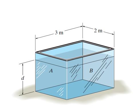
The tank is filled with water to a depth of Determine the resultant force the water exerts on side A and side B of the tank. If oil instead of water is placed in the tank, to what depth d should it reach so that it creates the same resultant forces? ρo = 900 kg/m3 and ρo = 1000 kg/m3. d A 3 m B 2
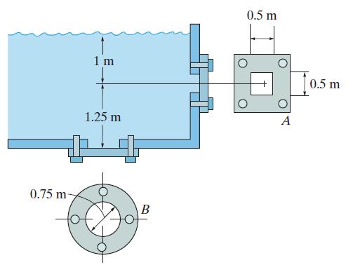
Determine the magnitude and location of the resultant hydrostatic force acting on each of the cover plates A and B. ρw =1.0 Mg/m3. 0.75 m- 1 m 1.25 m B 0.5 m O + O A 0.5 m
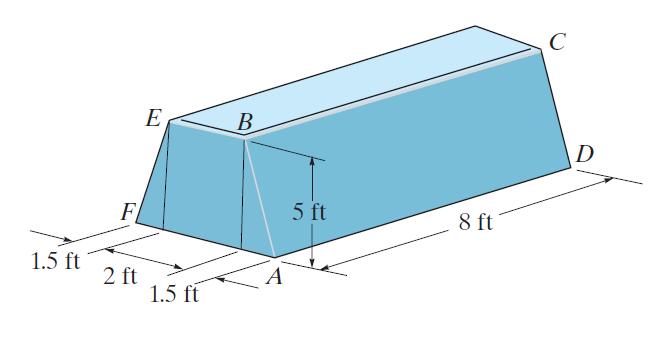
The tank is used to store a liquid having a specific weight of γ = 80 lb/ft3. If it is filled to the top, determine the magnitude of the resultant force the liquid exerts on side ABEF. 1.5 ft F 2 ft E 1.5 ft B A 5 ft 8 ft C D
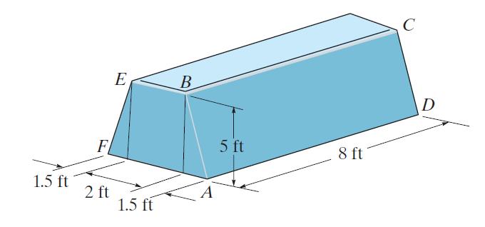
The trapezoidal back plate of the boat has the dimensions shown. If the water on the outside of the boat is 3 in. from the top, determine the resultant force on the plate and its location, measured from the top of the boat. ρw = 62.4 lb/ft3. 1.5 ft F 2 ft G₂ E 1.5 ft B A 5 ft 8 ft C D
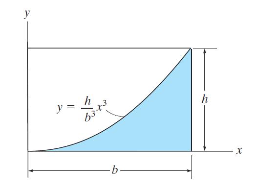
Determine the moment of inertia for the area about the y axis. y y = = h 6343 -b h X
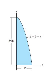
Determine the moment of inertia of the area about the y axis. 9 in. -3 in. =9-7² X
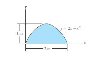
Determine the moment of inertia of the area about the y axis. 1m 2 m y = 2x-x² x
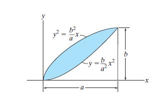
Determine the moment of inertia for the area about the x axis. 1². a TE b -X
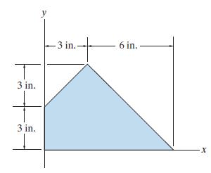
Determine the moment of inertia of the composite area about the x axis. T 3 in. 3 in. I y -3 in.. 6 in. X
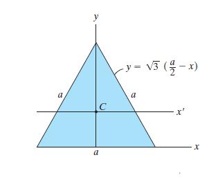
Determine the moment of inertia of the equilateral triangle about the x′ axis passing through its centroid. y C a - y = √3 (z - x) a
Determine the moment of inertia of the composite area about the y axis. T 3 in. 3 in. y -3 in. 6 in.. X
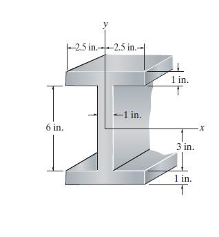
Determine the moment of inertia of the beam’s cross-sectional area with respect to the x and y centroidal axes. 6 in. y -2.5 in.-2.5 in.- -1 in. L 1 in. 3 in. 1 in. ·X
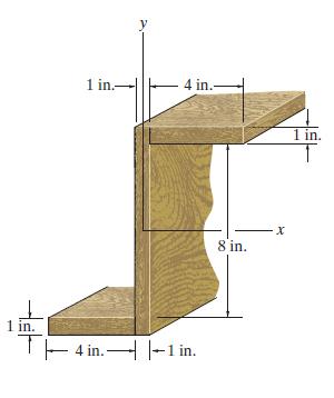
Determine the moment of inertia of the “Z” section with respect to the x and y centroidal axes. 1 in. 4 in.- 4 in.- 1 in. T-4 in. -1 in. 8 in. X 1 in.
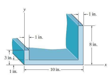
Determine the moment of inertia of the cross-sectional area of the beam about the y axis. 1 3 in. ↑ 1 in. y - 1 in. 10 in.- -1 in. 8 in. X
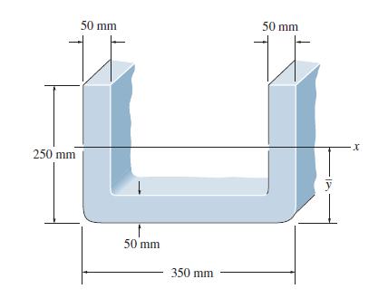
Determine the location of the centroid of the channel’s cross-sectional area and then calculate the moment of inertia of the area about this axis. 250 mm 50 mm 50 mm 350 mm 50 mm U ·X
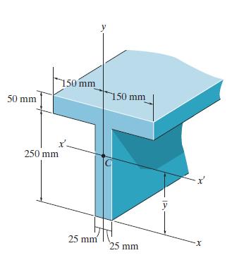
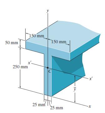
Determine the moment of inertia of the beam’s crosssectional area about the y axis. 50 mm 250 mm. 150 mm 25 mm y 150 mm 25 mm y -X
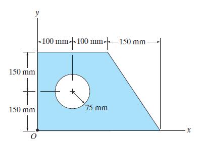
Determine the moment of inertia Iy of the shaded area about the y axis. 150 mm 150 mm O -100 mm-+-1 |- 100 mm-|-—150 mm - 75 mm ·X
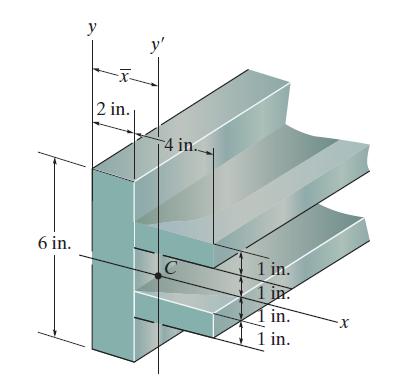
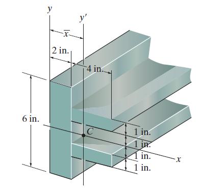
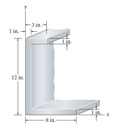
Determine the moment of inertia of the beam’s cross-sectional area about the x-axis. 6 in. y 2 in. y' 4 in.. C 1 in. 1 in. 1 in. 1 in. ·X
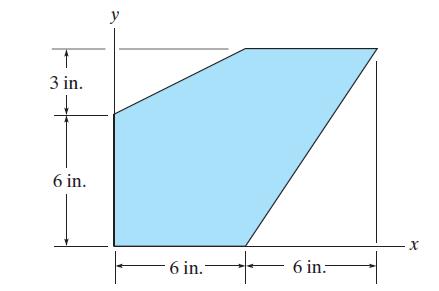
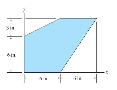
Determine the moment of inertia of the area about the x axis. T 3 in. 6 in. y 6 in. 6 in.- X
Determine y, which locates the centroidal axis x′ for the cross-sectional area of the T-beam, and then find the moment of inertia about the x′ axis. 50 mm 250 mm 150 mm 25 mm y 150 mm 25 mm -X
Determine the moment of inertia of the area about the y axis. T 3 in. 6 in. 6 in. 6 in.- X
Determine the distance x to the centroid for the beam’s cross-sectional area, then find I̅y. 6 in. y 2 in. y' 4 in. C 1 in. 1 in in. 1 in. X
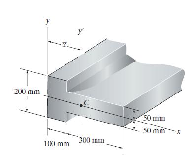
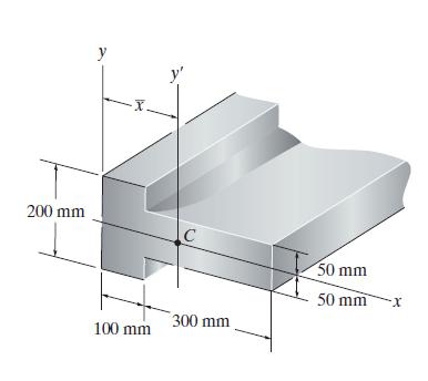
Determine the distance x to the centroid for the beam’s cross-sectional area, then find Iy. 200 mm y -X 100 mm y' C 300 mm 50 mm 50 mm ·x
Determine the moment of inertia of the beam’s crosssectional area about the x axis. 200 mm y ·X. 14 100 mm C 300 mm 50 mm 50 mm -X
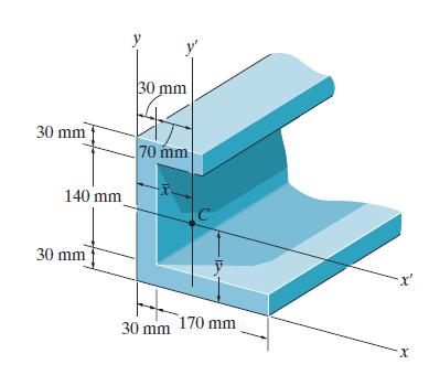
Determine the moment of inertia of the beam’s crosssectional area about the x axis. 30 mm 140 mm 30 mm y Js² 30 mm 70 mm 30 mm 170 mm X
Determine the moment of inertia of the beam’s crosssectional area about the y axis. 30 mm 140 mm 30 mm 30 mm K 70 mm 30 mm 170 mm -x² X
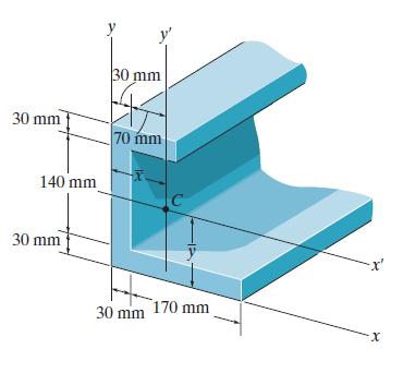
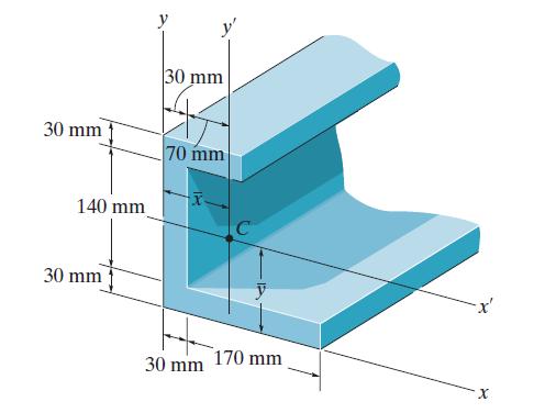
Determine the distance ȳ to the centroid C of the beam’s cross-sectional area and then compute the moment of inertia I̅x' about the x' axis. 30 mm 140 mm 30 mm 30 mm 70 mm 30 mm C 170 mm X
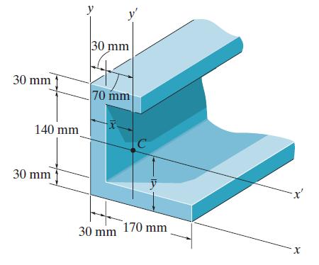
Determine the distance x̄ to the centroid C of the beam’s cross-sectional area and then find the moment of inertia I̅y' about the y' axis. 30 mm 140 mm 30 mm 30 mm 70 mm C 30 mm 170 mm X
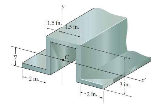
Determine the moment of inertia of the cross-sectional area of the wing channel about the y axis. 2 in. y 1.5 in. 1.5 in. C 2 in. 3 in.
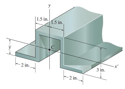
Determine ȳ which locates the centroid C of the crosssectional area of the wing channel, and then determine the moment of inertia I̅x′ about the centroidal x′ axis. Neglect the effect of rounded corners. The material has a uniform thickness of 0.5 in. y 2 in. 1.5 in. 1.5 in. C -2 in.. 3 in.
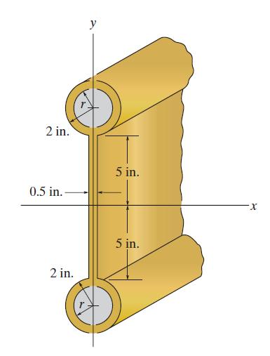
The assembly consists of two pipes and a plate. Determine the inner radii r of the pipes so that the moment of inertia of the assembly about the x axis is Ix = 527 in4. 2 in. 0.5 in. 2 in. y 5 in. 5 in. -X
Determine the polar moment of inertia of the shaft’s crosssectional area about the center O P ーー O a
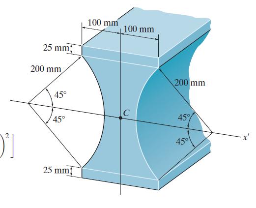
Determine the moment of inertia for the beam’s crosssectional area about the x′ axis that passes through the centroid C of the cross section. N 0²] 25 mm 200 mm, 45° 45° 25 mm 100 mm 100 mm C 200 mm 45% 45°
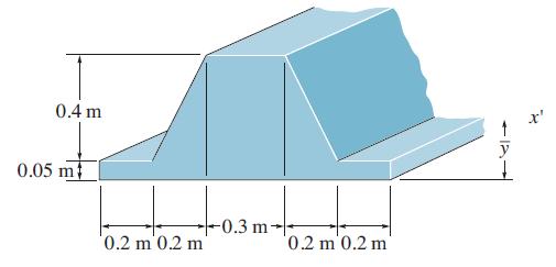
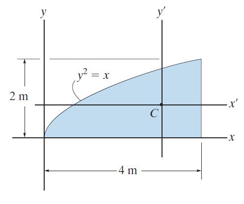
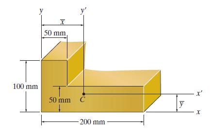
Locate the centroid ȳ of the cross section and determine the moment of inertia of the section about the x' axis. 0.4 m 0.05 m 0.2 m 0.2 m -0.3 m-- 0.2 m 0.2 m -12
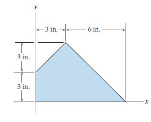
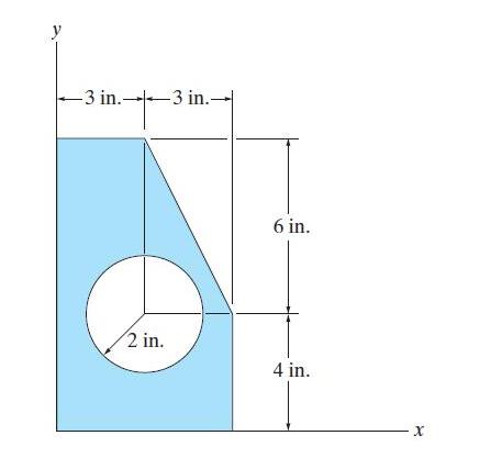
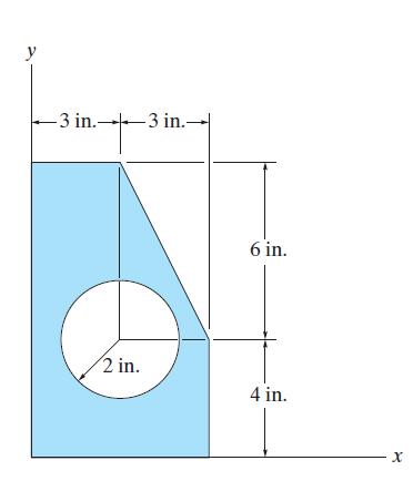
Determine the moment of inertia of the area about the x axis. -3 in.3 in. 2 in. 6 in. 4 in. ·X
Determine the moment of inertia of the area about the y axis. y -3 in.3 in.- 2 in. 6 in. 4 in. X
Determine the product of inertia of the area with respect to the x and y axes 1 m y -1m- y = x X
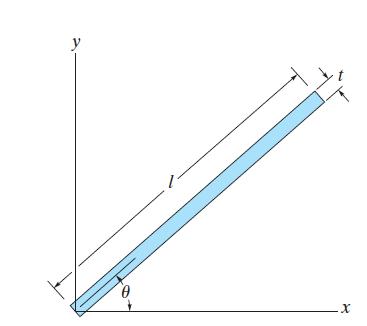
Determine the product of inertia of the thin strip of area t with respect to the and axes. The strip is oriented at an angle from the axis. Assume that t << l. y .x
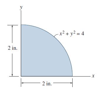
Determine the product of inertia of the shaded area with respect to the x and y axes. T 2 in. 2 in. -x² + y² = 4 X
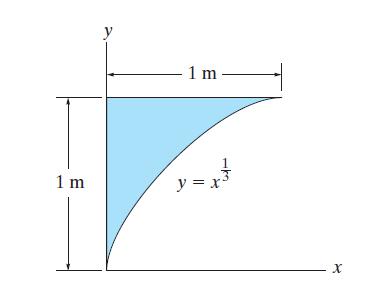
Determine the product of inertia of the area with respect to respect to the x and y axes, and then use the parallel-axis theorem to find the product of inertia of the area with respect to the centroidal x' and y' axes. 2 m y = X 4 m C - x' -X
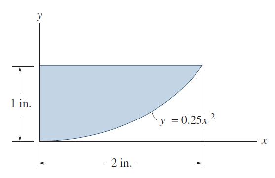
Determine the product of inertia of the shaded area with respect to the x and y axes. 1 in. y 2 in. y = 0.25x X
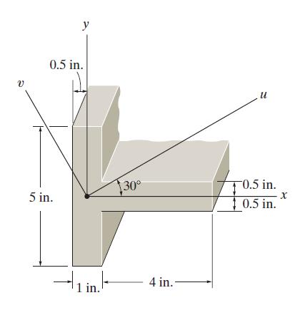
Determine the moments of inertia for the shaded area with respect to the u and v axes. v y 0.5 in. 5 in. 1 in. 30° 4 in.- u -0.5 in. 10.5 in. X
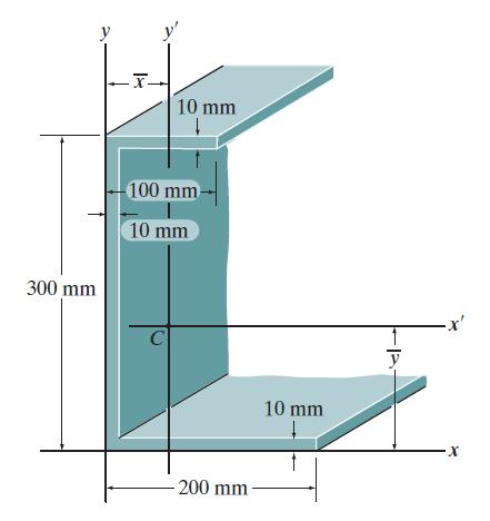
Locate the centroidal (x̄ and ȳ) of the beam's cross-sectional area, and then determine the product of inertia of this area with respect to the centroidal x' and y' axes. 300 mm y 10 mm 100 mm- 10 mm C 200 mm 10 mm y X
Determine the product of inertia for the shaded area with respect to the x and y axes. 1 in. y 12 in. -3 in.- F 8 in. 1 in. 1 in. X
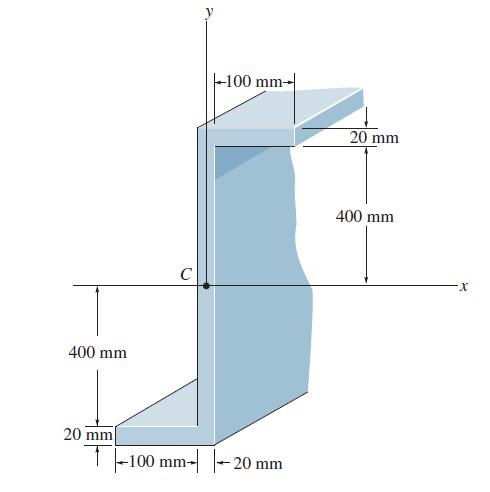
Determine the product of inertia of the cross-sectional area of the member with respect to the x and y axes. 400 mm 20 mm C -100 mm- -100 mm- -20 mm 20 mm 400 mm -X
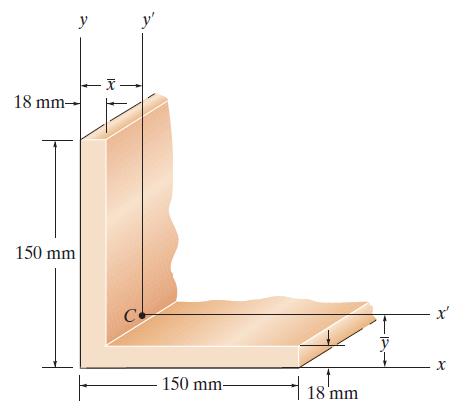
Determine the location (x̄ and ȳ) of the centroid C of the angle’s cross-sectional area, and then determine the product of inertia with respect to the x′ and y′ axes. 18 mm- 150 mm y C 150 mm- 18 mm y - x' x
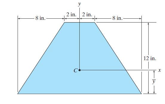
Locate the centroid, y, and determine the orientation of the principal centroidal axes for the composite area. What are the moments of inertia with respect to these axes? -8 in.. 2 in. 2 in. + 8 in.. 12 in. y X
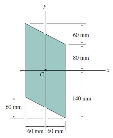
Determine the principal moments of inertia of the composite area with respect to a set of principal axes that have their origin located at the centroid C. Use the equations developed in Sec. 10.7. Ixy = -15.84(106) mm4. 60 mm y C 60 mm 60 mm 60 mm 80 mm 140 mm X
Locate the position x, y for the centroid C of the beam’s cross-sectional area, and then determine the product of inertia with respect to the x′ and y′ axes. 100 mm y X 50 mm, T 50 mm C -200 mm y x' X
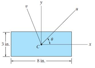
Determine the moments of inertia Iu and Iv and the product of inertia Iuv for the rectangular area. The u and v axes pass through the centroid C. Take θ = 30°. 3 in. И У C 8 in. Ө И X
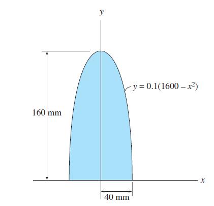
Determine the radius of gyration ky of the parabolic area. 160 mm y -y=0.1(1600-x²) 40 mm X
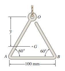
Determine the moment of inertia of the wire triangle about an axis perpendicular to the page and passing through point O.Also, locate the mass center G and determine the moment of inertia about an axis perpendicular to the page and passing through point G. The wire has a mass of 0.3 kg>m.
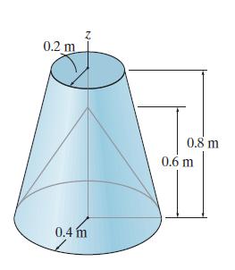
Determine the moment of inertia Iz of the frustum of the cone which has a conical depression. The material has adensity of ρ = 200 kg/m3. 0.2 m Z 0.4 m 0.8 m 0.6 m
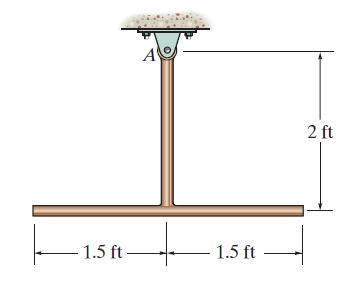
The slender rods have a weight of 3 Ib/ft. Determine the moment of inertia of the assembly about an axis perpendicular to the page and passing through point A. -1.5 ft- A - 1.5 ft 2 ft
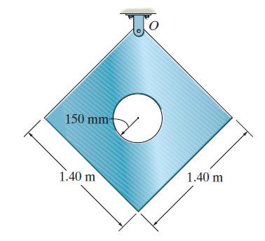
Determine the moment of inertia of the thin plate about an axis perpendicular to the page and passing through the pin at O. The plate has a hole in its center. Its thickness is 50 mm, and the material has a density of r = 50 kg/m3. 150 mm- 1.40 m 1.40 m
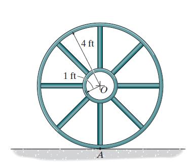
If the large ring, small ring and each of the spokes weigh 100 lb, 15 lb, and 20 lb, respectively, determine the mass moment of inertia of the wheel about an axis perpendicular to the page and passing through point A. 1 ft- 4 ft A
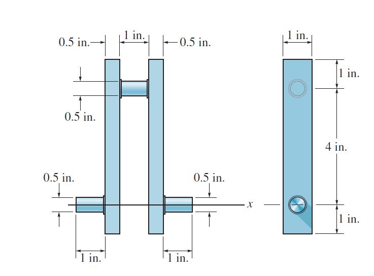
Determine the moment of inertia of the wheel about the x axis that passes through the center of mass G. The material has a specific weight of γst = 490 lb/ft3. 0.5 in.- 0.5 in. 0.5 in. 1 in. 1 in. 0.5 in. 1 in. 0.5 in. X 1 in. 1 in. 4 in. 1 in.
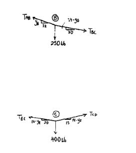
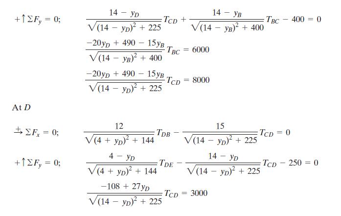
The cable supports the three loads shown. Determine the sags yB and yD of points B and D. Take P1 = 400 lb, P2 = 250 lb.Combining Eqs. (1) & (2)Combining Eqs. (3) & (4) 4 ft A УВ B P₂ -12 ft-- -20 ft- 14 ft P₁ YD P₂ 15 ft- accpooo!! 12 ft- E
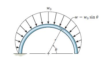
The semicircular rod is subjected to a distributed loadin w = w0 sin θ. Determine the normal force, shear force. and moment in the rod as a function of θ. Wo -W Wo sin 0
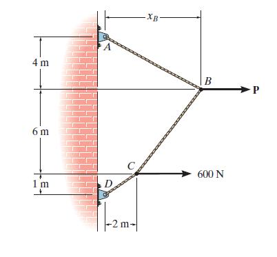
The cable supports the loading shown. Determine the magnitude of the horizontal force P so that xB = 5 m. 4 m 6 m 1 m 4 A -2 m- XB B 600 N
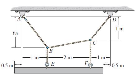
Cable ABCD supports the 120-kg uniform beam. Determine the maximum tension in this cable and the sag of point B. Ув 0.5 m -1 m- B E -2 m F C -1 m- D 1 m 0.5 m
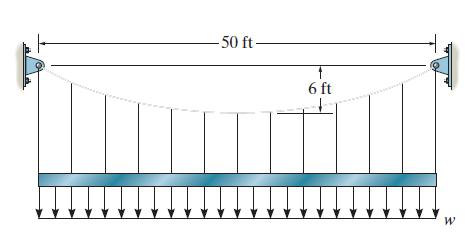
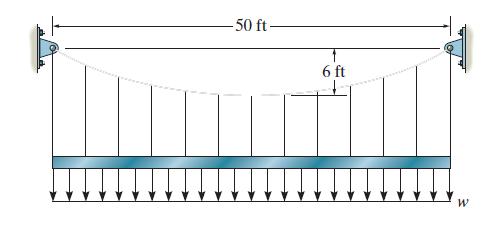
Determine the maximum uniform loading w, measured in that the cable can support if it is capable of sustaining a maximum tension of 3000 lb before it will break. -50 ft- 6 ft W
The cable is subjected to a uniform loading of w = 250 Ib/ft. Determine the maximum and minimum tension in the cable. 50 ft- 6 ft + W
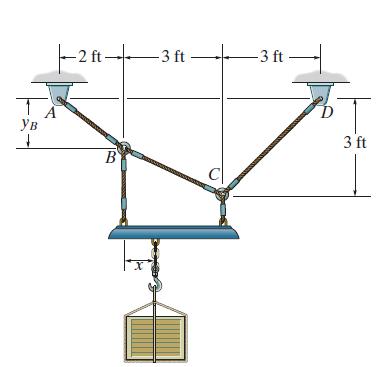
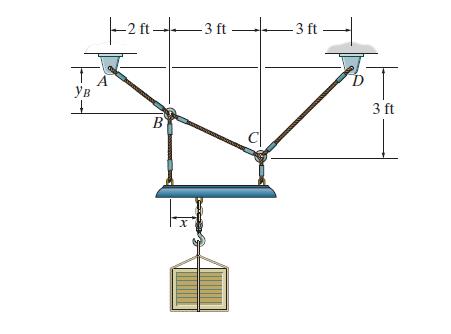
If yB = 1.5 ft, determine the largest weight of the crate and its placement x so that neither cable segment AB, BC, or CD is subjected to a tension that exceeds 200 lb. 1 Ув 1 |--2 ft- B -3 ft-+ -3 ft т 3 ft
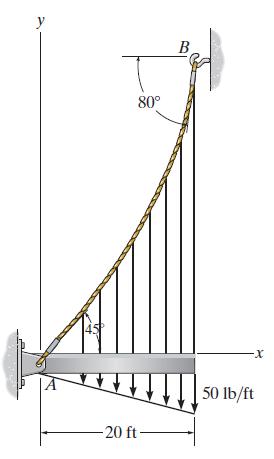
The cable AB is subjected to a triangular loading. If the angles with the tangents at points A and B are 45° and 80°, respectively, determine the deflection curve of the cable and the maximum tension developed in the cable. y 80° -20 ft- B -X 50 lb/ft
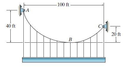
The cable supports a girder which weighs 850 Determine the tension in the cable at points A,B, and C. 40 ft -100 ft- B 20 ft L
If x = 2 ft and the crate weighs 300 lb, which cable segment/ AB, BC, or CD has the greatest tension? What is this force and what is the sag yB? T Ув ㅗ |--2 ft- A B 3 ft -3 ft- 3 ft
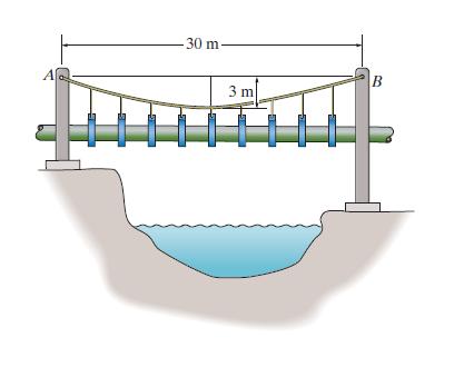
If the pipe has a mass per unit length of 1500 kg m, determine the maximum tension developed in the cable. 30 m- 3 m B
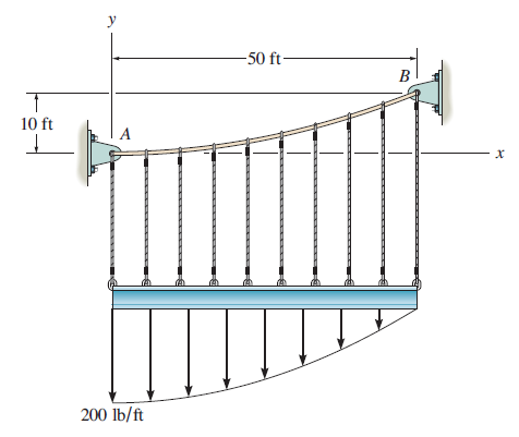
The cable is subjected to the parabolic loading w = 200(1 - (x/502) lb/ft, where x is in ft. Determine the equation y = f(x) which defines the cable shape AB, and the maximum tension in the cable. The slope of the cable at A is zero. T 10 ft I A 200 lb/ft -50 ft- B X
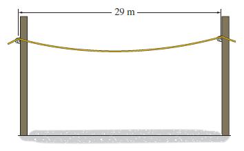
The power line has a mass of 500 g/m. If it has a length of 32 m between the poles, determine the maximum tension in the line and its sag. 29 m
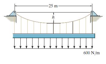
The cable will break when the maximum tension reaches Tmax = 10kN. Determine the minimum sag h if it supports the uniform distributed load of w = 600 N/m. -25 m- h 600 N/m
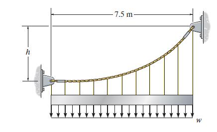
The cable will break when the maximum tension reaches Tmax = 12 kN. Determine the uniform distributed load w required to develop this maximum tension. Set h = 6 m. h -7.5 m- ↓↓ W
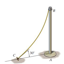
The cable has a weight of 8 N/m and length of 10 m. If the tension in the cable at C is 300 N, determine the distance from A to C. с 30⁰ A B
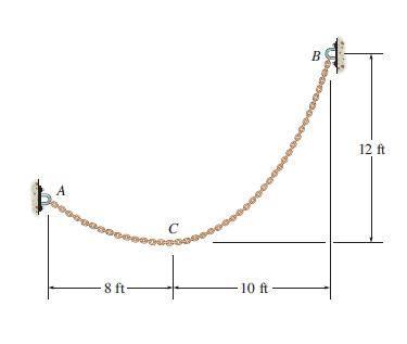
The chain has a weight of 3 lb/ft. Determine the tension at points A, B, and C. A epper - 8 ft- C 000000 10 ft B 12 fit
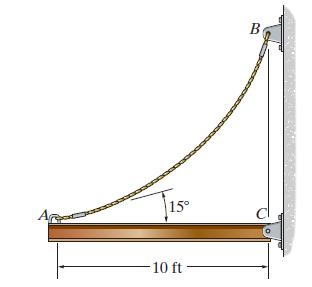
The uniform beam weighs 80 lb/ft and is held in the horizontal position by means of cable AB, which has a weight of 10 lb/ft. If the slope of the cable at A is 15°, determine the length of the cable. 15° -10 ft B
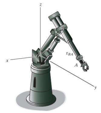
Position vectors along the robotic arm from O to B and B to A arc r0B = (100i +300j + 400k} mm and nBA = {350i + 225j - 640k) mm, respectively. Determine the distance from O to the grip at A. Х N IBA A
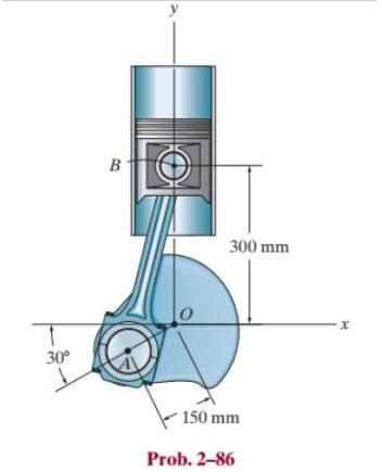
Determine the distance between the end points A and B on the pipe assembly. 30° B 300 mm 150 mm Prob. 2-86 X
Showing 200 - 300
of 708
1
2
3
4
5
6
7
8
Step by Step Answers