

Question: The following circuit diagram represents a closed loop system for lighting control in an otherwise dark room. Assume you want a lightbulb to provide constant
The following circuit diagram represents a closed loop system for lighting control in an otherwise dark room. Assume you want a lightbulb to provide constant illumination of strength LD even if the strength of the lightbulb appreciably changes with age. Light control is achieved by a suitable light sensitive sensor that compares the bulb’s measured output LB to the desired light level, LD. The input signal is the difference between LD and LB and is communicated to a variable circuit voltage from 0 – 100.V, which in turn sets the voltage, the current, and finally the bulb’s intensity. Draw a block diagram of the control, indicating on the diagram which parts of the conceptual sketch correspond to the blocks. If the sensor compares two inputs, does it remind you of a comparator?
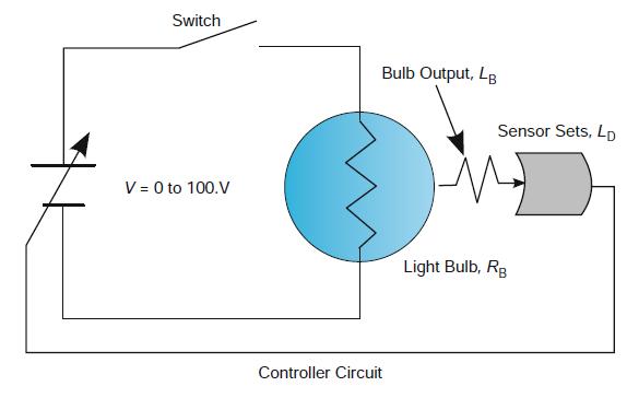
Switch Bulb Output, LB Sensor Sets, Lp V = 0 to 100.V Light Bulb, Rg Controller Circuit
Step by Step Solution
3.44 Rating (167 Votes )
There are 3 Steps involved in it
The circuit diagram you provided outlines a closedloop system for a light control mechanism To explain and draw the corresponding block diagram well b... View full answer

Get step-by-step solutions from verified subject matter experts