

Computer analysis of a truss with rigid joints. The truss in Figure P4.55 is constructed of square
Question:
Computer analysis of a truss with rigid joints. The truss in Figure P4.55 is constructed of square steel tubes welded to form a structure with rigid joints. The top chord members 1, 2, 3, and 4 are 4×4×1/4 square tubes with A = 3.37 in.2 and I = 7.80 in.4. All other members are 3×3×1/4 square tubes with A = 2.44 in.2 and I = 3.02 in.4. Use E = 29,000 kips/in.2.
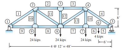
(a) Considering all joints as rigid, compute the axial forces and moments in all bars and the deflection at midspan when the three 24-kip design loads act at joints 7, 8, and 9 (ignore the 4-kip load). (b) If a hoist is also attached to the lower chord at the midpoint of the end panel on the right (labeled joint 6*) to raise a concentrated load of 4 kips, determine the forces and moments in the lower chord (members 5 and 6). If the maximum stress is not to exceed 25 kips/in.2, can the lower chord support the 4-kip load safely in addition to the three 24-kip loads? Compute the maximum stress, using the equation
![]()
where c = 1.5 in. (one-half the depth of the lower chord).
Step by Step Answer:
Computer Analysis of Truss with Rigid Joints a b Deflection at midspan Joint 8 ...View the full answer


Fundamentals Of Structural Analysis
ISBN: 9780073398006
5th Edition
Authors: Kenneth Leet, Chia-Ming Uang, Joel Lanning
