

Question: A logic circuit has two inputs, Clock and Start, and two outputs, f and g. The behavior of the circuit is described by the timing
A logic circuit has two inputs, Clock and Start, and two outputs, f and g. The behavior of the circuit is described by the timing diagram in Figure P5.8. When a pulse is received on the Start input, the circuit produces pulses on the f and g outputs as shown in the timing diagram. Design a suitable circuit using only the following components: a three bit resettable positive-edge-triggered synchronous counter and basic logic gates. For your answer assume that the delays through all logic gates and the counter are negligible.
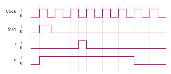
Clock 1 0 Start f g 1 0 0 1 0 H
Step by Step Solution
3.36 Rating (149 Votes )
There are 3 Steps involved in it
One way to design the logic circuit is to use a 3bit resettable positiveedgetriggered synchronous co... View full answer

Get step-by-step solutions from verified subject matter experts