

Question: Example 4.35 and Figure 4.56 show how a circuit that generates an ASCII byte suitable for sending over a communications link may be defined. Write
Example 4.35 and Figure 4.56 show how a circuit that generates an ASCII byte suitable for sending over a communications link may be defined. Write Verilog code for its counterpart at the receiving end, where byte Y (which includes the parity bit) has to be converted into byte X in which the bit x7 has to be 0. An error signal has to be produced, which is set to 0 or 1 depending on whether the parity check indicates correct or erroneous transmission, respectively.
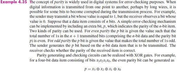
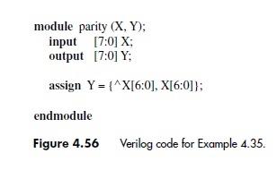
Example 4.35 The concept of parity is widely used in digital systems for error-checking purposes. When digital information is transmitted from one point to another, perhaps by long wires, it is possible for some bits to become corrupted during the transmission process. For example, the sender may transmit a bit whose value is equal to 1, but the receiver observes a bit whose value is 0. Suppose that a data item consists of a bits. A simple error-checking mechanism can be implemented by including an extra bit, p, which indicates the parity of the n-bit item. Two kinds of parity can be used. For even parity the p bit is given the value such that the total number of 1s in the n + 1 transmitted bits (comprising the n-bit data and the parity bit p) is even. For odd parity the p bit is given the value that makes the total number of 1s odd. The sender generates the p bit based on the n-bit data item that is to be transmitted. The receiver checks whether the parity of the received item is correct. Parity generating and checking circuits can be realized with XOR gates. For example, for a four-bit data item consisting of bits x3xxx, the even parity bit can be generated as P = X3 XX1 X
Step by Step Solution
3.34 Rating (151 Votes )
There are 3 Steps involved in it
Here is the Verilog code for the receiver end of the circuit described in Example 435 and Figur... View full answer

Get step-by-step solutions from verified subject matter experts