

Question: In Example 9.22 we merged states D and H to implement the FSM in Figure 9.82. An alternative was to merge states B and H,
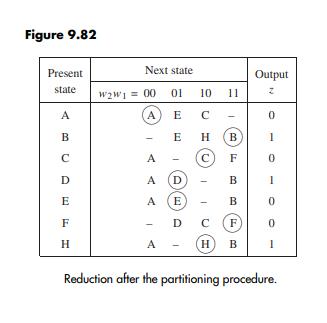
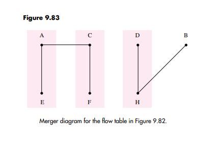
In Example 9.22 we merged states D and H to implement the FSM in Figure 9.82. An alternative was to merge states B and H, according to the merger diagram in Figure 9.83. Derive an implementation using this choice. Derive the resulting excitation table.
Example 9.22
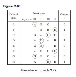
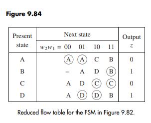
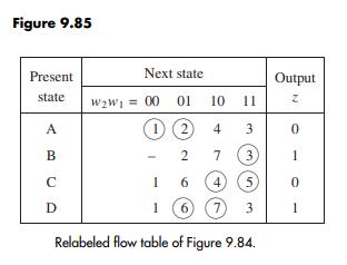
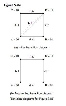
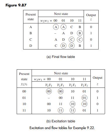
Problem: Consider the flow table in Figure 9.81. Reduce this flow table and find a state assignment that allows this FSM to be realized as simply as possible, preserving the Moore model. Derive an excitation table.Solution: Using the partioning procedure on the flow table in Figure 9.81 givesP1 = (ACEFG)(BDH)P2 = (AG)(B)(C)(D)(E)(F)(H)P3 = P2Combining A and G produces the flow table in Figure 9.82. Amerger diagram for this table is shown in Figure 9.83. Merging the states (A, E), (C, F), and (D,H) leads to the reduced flow table in Figure 9.84. To find a good state assignment, we relabel this flow table as indicated in Figure 9.85, and construct the transition diagram in Figure 9.86a. The only problem in this diagram is the transition from state D to state A, labeled as 1. Achange from D to A can be made via state C if we specify so in the flow table. Then, a direct transition from D to A is not needed, as depicted in Figure 9.86b. The resulting flow table and the corresponding excitation table are shown in Figure 9.87.
Present state A B C D E F H Next state 10 (A) E C E W2W1 = 00 01 1 H (B A C F A D B A E B D C (F HB A - 11 - 1 Output Z 0 1 0 1 0 0 1
Step by Step Solution
3.50 Rating (160 Votes )
There are 3 Steps involved in it
To derive the implementation by merging states B and H based on the merger diagram in Figure 983 fol... View full answer

Get step-by-step solutions from verified subject matter experts