

Question: Prove Shannons expansion theorem presented in Section 4.1.2. Section 4.1.2 Figures 4.6 through 4.9 illustrate how truth tables can be interpreted to implement logic functions
Prove Shannon’s expansion theorem presented in Section 4.1.2.
Section 4.1.2
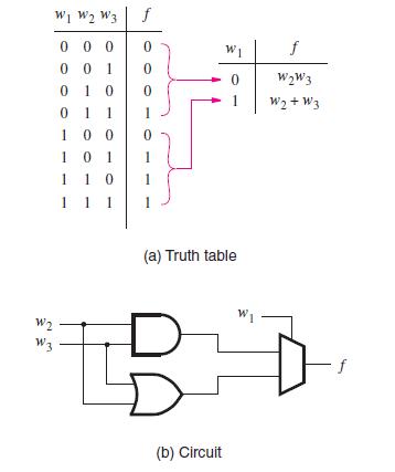
Figures 4.6 through 4.9 illustrate how truth tables can be interpreted to implement logic functions using multiplexers. In each case the inputs to the multiplexers are the constants 0 and 1, or some variable or its complement. Besides using such simple inputs, it is possible to connect more complex circuits as inputs to a multiplexer, allowing functions to be synthesized using a combination of multiplexers and other logic gates. Suppose that we want to implement the three-input majority function in Figure 4.7 using a 2-to-1 multiplexer in this way. Figure 4.10 shows an intuitive way of realizing this function. The truth table can be modified as shown on the right. If w1 = 0, then f = w2w3, and if w1 = 1, then f = w2 + w3. Using w1 as the select input for a 2-to-1 multiplexer leads to the circuit in Figure 4.10b.
This implementation can be derived using algebraic manipulation as follows. The function in Figure 4.10a is expressed in sum-of-products form as
f = w1w2w3 + w1w2w3 + w1w2w3 + w1w2w3
It can be manipulated into
f = w1(w2w3) + w1(w2w3 + w2w3 + w2w3)
= w1(w2w3) + w1(w2 + w3)
which corresponds to the circuit in Figure 4.10b.
Multiplexer implementations of logic functions require that a given function be decomposed in terms of the variables that are used as the select inputs. This can be accomplished by means of a theorem proposed by Claude Shannon [1].
W W W3 f 000 001 W2 W3 0 10 0 1 1 100 101 1 10 1 1 1 0 0 0 1 0 1 (a) Truth table D D 0 (b) Circuit f W2W3 W2+W3
Step by Step Solution
3.47 Rating (160 Votes )
There are 3 Steps involved in it
In Java Shannons expansion theorem can be applied in the context of digital logic design by using boolean expressions to represent logic functions and ... View full answer

Get step-by-step solutions from verified subject matter experts