

Question: The circuit designed in Section 7.6 uses an adder to compute the sum of the contents of the registers. The divider sub circuit used to
The circuit designed in Section 7.6 uses an adder to compute the sum of the contents of the registers. The divider sub circuit used to compute M = Sum/k also includes an adder. Show how the circuit can be redesigned so that it contains only a single adder sub circuit that is used both for the summation operation and the division operation. Show only the extra circuitry needed to connect to the adder; and explain its operation.
Data From Section 7.6
Assume that k n-bit numbers are stored in a set of registers R0, . . . , Rk−1. We wish to design a circuit that computes the mean M of the numbers in the registers. The pseudo-code for a suitable algorithm is shown in Figure 7.37a. Each iteration of the loop adds the contents of one of the registers, denoted Ri, to a Sum variable. After the sum is computed, M is obtained as Sum/k. We assume that integer division is used, so a remainder R, not shown in the code, is produced as well.
An ASM chart is given in Figure 7.37b. While the start input, s, is 0, the registers can be loaded from external inputs. When s becomes 1, the machine changes to state S2, where it remains while C ≠ 0, and computes the summation (C is a counter that represents i in Figure 7.37a). When C = 0, the machine changes to state S3 and computes M = Sum/k. From the previous example, we know that the division operation requires multiple clock cycles, but we have chosen not to indicate this in the ASM chart. After computing the division operation, state S4 is entered and Done is set to 1.
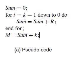
Sum = 0; for i = k - 1 down to 0 do Sum = Sum + Ri end for; M = Sum k;| (a) Pseudo-code
Step by Step Solution
3.45 Rating (164 Votes )
There are 3 Steps involved in it
The extra circuitry needed to connect the adder for both the summation and division operations i... View full answer

Get step-by-step solutions from verified subject matter experts