

Question: Write Verilog code that defines the serial subtractor designed in Problem 6.40. Data From Problem 6.40 Section 6.5 presents a design for the serial adder.
Write Verilog code that defines the serial subtractor designed in Problem 6.40.
Data From Problem 6.40
Section 6.5 presents a design for the serial adder. Derive a similar circuit that functions as a serial subtractor which produces the difference of operands A and B.
Data From Section 6.5
Serial Adder Example
We will now present another simple example that illustrates the complete design process. In Chapter 3 we discussed the addition of binary numbers in detail. We explained several schemes that can be used to add two n-bit numbers in parallel, ranging from carry-ripple to carry-lookahead adders. In these schemes the speed of the adder unit is an important design parameter. Fast adders are more complex and thus more expensive. If speed is not of great importance, then a cost-effective option is to use a serial adder, in which bits are added a pair at a time.
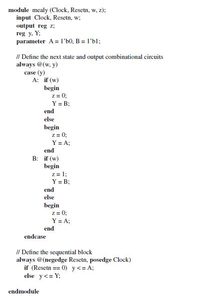
module mealy (Clock, Resetn, w, z); input Clock, Resetn, w; output reg z; reg y, Y; parameter A l'b0, B = 1'bl; // Define the next state and output combinational circuits always @(w, y) case (y) A: if (w) begin z = 0; Y = B: end else begin endmodule end B: if (w) begin z = 0; Y = A: endcase z = 1; Y = B; end else begin z = 0; Y = A; end // Define the sequential block always @(negedge Resetn, posedge Clock) if (Resetn == 0) y
Step by Step Solution
3.42 Rating (158 Votes )
There are 3 Steps involved in it
To design a serial subtractor in Verilog we need to modify the serial adder design presented in Sect... View full answer

Get step-by-step solutions from verified subject matter experts