

The equations describing the circuit shown in Figure P37 are a. The given values of the resistances
Question:
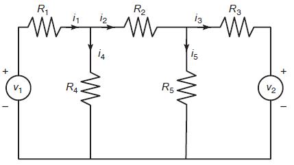
The equations describing the circuit shown in Figure P37 are
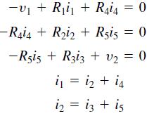
a. The given values of the resistances and the voltage υ1 are R1 = 5. R2 = 100, R3 = 200, R4 = 150, R5 = 250 kΩ, and υ1 = 100V.
(Note that 1 kΩ = 1000 0.) Suppose that each resistance is rated to carry a current of no more than 1 mA (= 0.001 A). Determine the allowable range of positive values for the voltage 2.
b. Suppose we want to investigate how the resistance R3 limits the allowable range for υ2. Obtain a plot of the allowable limit on υ2 as a function of R3 150 ≤ R3 ≤ 250 for kΩ.
Figure P37
Fantastic news! We've Found the answer you've been seeking!
Step by Step Answer:
Part a Part b Lets define the maximum currents through each branch as follows Imax 000...View the full answer

Answered By
Muhammad Umair
I have done job as Embedded System Engineer for just four months but after it i have decided to open my own lab and to work on projects that i can launch my own product in market. I work on different softwares like Proteus, Mikroc to program Embedded Systems. My basic work is on Embedded Systems. I have skills in Autocad, Proteus, C++, C programming and i love to share these skills to other to enhance my knowledge too.
1+ Reviews
10+ Question Solved
Related Book For 
Question Posted:
