

Question: The state table for a sequential circuit is given in Table 4-16. (a) Draw the state diagram for the circuit. (b) Implement the circuit using
The state table for a sequential circuit is given in Table 4-16.
(a) Draw the state diagram for the circuit.
(b) Implement the circuit using D lip- lops and minimal input functions for each lip- lop. Reset is asynchronous and active low (RESET = 0), and initializes the state to A = 0, B = 0.
Table 4-16:
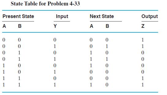
State Table for Problem 4-33 Present State A B 0 0 0 0 1 1 1 1 0 0 1 1 0 0 1 1 Input Y 0 1 0 1 0 1 0 1 Next State A B T100TOOL 0 1 0 1 0 0 0 0 Output N 1 1 0 0 0 0 1 1
Step by Step Solution
3.57 Rating (161 Votes )
There are 3 Steps involved in it
a 1 0 b D ABB... View full answer

Get step-by-step solutions from verified subject matter experts