

A cantilever beam AB is loaded by a uniform load q and a concentrated load P, as
Question:
A cantilever beam AB is loaded by a uniform load q and a concentrated load P, as shown in the figure.
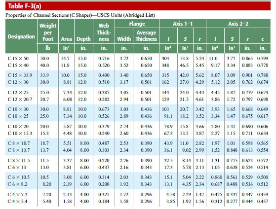
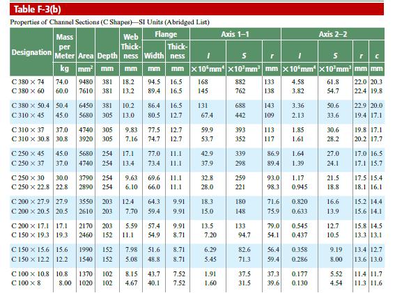
(a) Select the most economical steel C shape from Table F-3(a) in Appendix F; use q 5 20 lb/ft and P = 300 lb (assume allowable normal stress is s a 518 ksi).
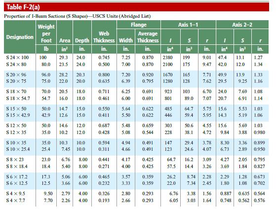
(b) Select the most economical steel S shape from Table F-2(a) in Appendix F; use q 5 45 lb/ft and P = 2000 lb (assume allowable normal stress is
s a =. 20 ksi).
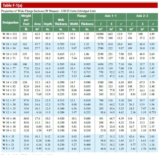
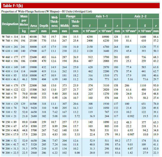
(c) Select the most economical steel W shape. Table F-1(a) in Appendix F; use q = 45 lb/ft and P = 2000 lb (assume allowable normal stress is s a = 20 ksi). However, assume that the design requires that the W shape must be used in weak axis bending, i.e., it must bend about the 2–2 (or y) axis of the cross section.
Fantastic news! We've Found the answer you've been seeking!
Step by Step Answer:
a Select THIE MOST ...View the full answer

Answered By
Kainat Shabbir
i am an experienced qualified expert with a long record of success helping clients overcome specific difficulties in information technology, business and arts greatly increasing their confidence in these topics. i am providing professional services in following concerns research papers, term papers, dissertation writing, book reports, biography writing, proofreading, editing, article critique, book review, coursework, c++, java, bootstarp, database.
184+ Reviews
255+ Question Solved
Related Book For 
Question Posted:
