New Semester
Started
Get
50% OFF
Study Help!
--h --m --s
Claim Now
Question Answers
Textbooks
Find textbooks, questions and answers
Oops, something went wrong!
Change your search query and then try again
S
Books
FREE
Study Help
Expert Questions
Accounting
General Management
Mathematics
Finance
Organizational Behaviour
Law
Physics
Operating System
Management Leadership
Sociology
Programming
Marketing
Database
Computer Network
Economics
Textbooks Solutions
Accounting
Managerial Accounting
Management Leadership
Cost Accounting
Statistics
Business Law
Corporate Finance
Finance
Economics
Auditing
Tutors
Online Tutors
Find a Tutor
Hire a Tutor
Become a Tutor
AI Tutor
AI Study Planner
NEW
Sell Books
Search
Search
Sign In
Register
study help
engineering
mechanics of materials
Engineering Mechanics Dynamics 14th Global Edition Hibbeler - Solutions
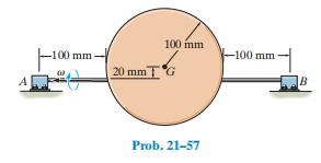
21–57. The 5-kg circular disk is mounted off center on a shaft which is supported by bearings at A and B. If the shaft is rotating at a constant rate of v = 10 rad>s, determine the vertical reactions at the bearings when the disk is in the position shown. -100 mm 100 mm -100 mm- 20 mm T*G
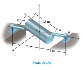
The cylinder has mass of 30 kg and is mounted on an axle that is supported by bearings at A and B. If the axle is subjected to a couple moment M = {-30j} N#m, and at the instant shown has an angular velocity v = {-40j} rad>s, determine the vertical components of force acting at the bearings at
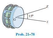
21–78. The radius of gyration about an axis passing through the axis of symmetry of the 1.2-Mg satellite is kz = 1.4 m, and about any transverse axis passing through the center of mass G, kt = 2.20 m. If the satellite has a known spin of 2700 rev>h about the z axis, determine the steady-state
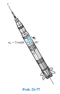
21–77. While the rocket is in free flight, it has a spin of 3 rad>s and precesses about an axis measured 10° from the axis of spin. If the ratio of the axial to transverse moments of inertia of the rocket is 1>15, computed about axes which pass through the mass center G, determine the
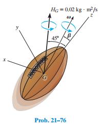
*21–76. The football has a mass of 450 g and radii of gyration about its axis of symmetry (z axis) and its transverse axes (x ory axis) of kz = 30 mm and kx = ky = 50 mm, respectively. If the football has an angular momentum of HG = 0.02 kg#m2>s, determine its precession f#and spin c#. Also,
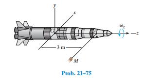
21–75. The rocket has a mass of 4 Mg and radii of gyration kz = 0.85 m and kx = ky = 2.3 m. It is initially spinning about the z axis at vz = 0.05 rad>s when a meteoroid M strikes it at A and creates an impulse I = 5300i6 N#s.Determine the axis of precession after the impact. -3 m M Prob.
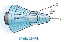
21–74. The radius of gyration about an axis passing through the axis of symmetry of the 1.6-Mg space capsule is kz = 1.2 m and about any transverse axis passing through the center of mass G, kt = 1.8 m. If the capsule has a known steady-state precession of two revolutions per hour about the Z
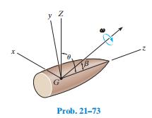
21–73. The projectile shown is subjected to torque-free motion. The transverse and axial moments of inertia are I and Iz, respectively. If u represents the angle between the precessional axis Z and the axis of symmetry z, and b is the angle between the angular velocity V and the z axis, show
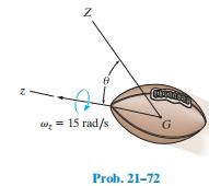
*21–72. The 0.25 kg football is spinning at vz = 15 rad>s as shown. If u = 40 , determine the precession about thez axis. The radius of gyration about the spin axis is kz = 0.042 m, and about a transverse axis is ky = 0.13 m. Z w = 15 rad/s G Prob. 21-72
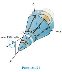
21–71. The space capsule has a mass of 2 Mg, center of mass at G, and radii of gyration about its axis of symmetry(z axis) and its transverse axes (x or y axis) of kz = 2.75 m and kx = ky = 5.5 m, respectively. If the capsule has the angular velocity shown, determine its precession f#and spin
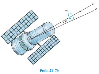
21–70. The satellite has a mass of 1.8 Mg. The axial and transverse radii of gyration about axes passing through the mass center G are kz = 0.8 m and kt = 1.2 m, respectively.If it is spinning at vs = 6 rad>s when it is launched, determine its angular momentum. Precession occurs about the Z
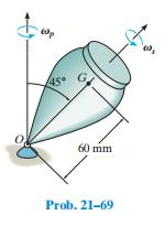
21–69. The top has a mass of 90 g, a center of mass at G, and a radius of gyration k = 18 mm about its axis of symmetry. About any transverse axis acting through point O the radius of gyration is kt = 35 mm. If the top is connected to a ball-and-socket joint at O and the precession is vp = 0.5
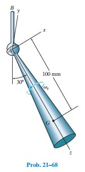
*21–68. The conical top has a mass of 0.8 kg, and the moments of inertia are Ix = Iy = 3.5(10-3) kg#m2 and Iz = 0.8(10-3) kg#m2 . If it spins freely in the ball-and socket joint at A with an angular velocity vs = 750 rad>s, compute the precession of the top about the axis of the shaft AB. B
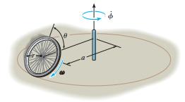
21–67. A wheel of mass m and radius r rolls with constant spin V about a circular path having a radius a. If the angle of inclination is u, determine the rate of precession. Treat the wheel as a thin ring. No slipping occurs.
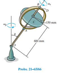
21–66.When OA precesses at a constant rate of vp = 5 rad>s, when u = 90 , determine the required spin of the 10-kg disk C. Neglect the mass of arm OA, axle AB, and the circular ring D. wp B D 600 mm Probs. 21-65/66 -150 mm
21–65. The 10-kg disk spins about axle AB at a constant rate of vs = 250 rad>s, and u = 30 . Determine the rate of precession of arm OA. Neglect the mass of arm OA, axleAB, and the circular ring D. wp B D 600 mm Probs. 21-65/66 -150 mm
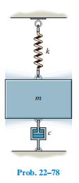
22–78. Draw the electrical circuit that is equivalent to the mechanical system shown. Determine the differential equation which describes the charge q in the circuit. m Prob. 22-78
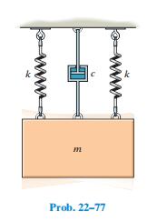
22–77. Draw the electrical circuit that is equivalent to the mechanical system shown. What is the differential equation which describes the charge q in the circuit? Prob. 22-77
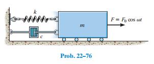
22–76. Draw the electrical circuit that is equivalent to the mechanical system shown. Determine the differential equation which describes the charge q in the circuit. C m F = Focos cat Prob. 22-76
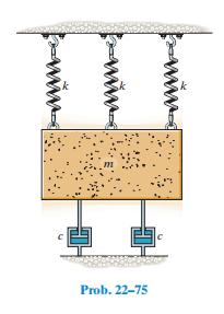
22–75. Determine the differential equation of motion for the damped vibratory system shown. What type of motion occurs? Take k = 100 N>m, c = 200 N#s>m, m = 25 kg. Prob. 22-75
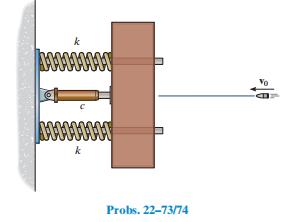
22–74.A bullet of mass m has a velocity v0 just before it strikes the target of mass M. If the bullet embeds in the target, and the dashpot’s damping coefficient is 0 6 c cc, determine the springs’ maximum compression. The target is free to move along the two horizontal guides that
22–73. A bullet of mass m has a velocity of v0 just before it strikes the target of mass M. If the bullet embeds in the target, and the vibration is to be critically damped, determine the dashpot’s critical damping coefficient, and the springs’maximum compression. The target is free to move
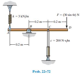
*22–72. If the 12-kg rod is subjected to a periodic force ofF = (30 sin 6t) N, where t is in seconds, determine the steady-state vibration amplitude umax of the rod about the pin B. Assume u is small. k = 3 kN/m 0.2 m -0.2 m B C Prob. 22-72 F = (30 sin 6r) N -0.2 m D c = 200 N's/m
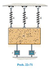
22–71. Determine the differential equation of motion for the damped vibratory system shown. What type of motion occurs? Take k = 100 N>m, c = 200 N # s>m, m = 25 kg. Prob. 22-71
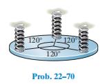
22–70. The 4-kg circular disk is attached to three springs,each spring having a stiffness k = 180 N>m. If the disk is immersed in a fluid and given a downward velocity of 0.3 m>s at the equilibrium position, determine the equation which describes the motion. Consider positive displacement
22–69. The damping factor, c>cc, may be determined experimentally by measuring the successive amplitudes of vibrating motion of a system. If two of these maximum displacements can be approximated by x1 and x2, as shown in Fig. 22–16, show that ln (x1>x2) = 2p(c>cc)> 21- (c>cc)2 . The quantity
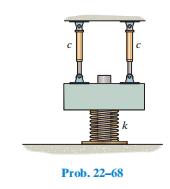
*22–68. Two identical dashpots are arranged parallel to each other, as shown. Show that if the damping coefficient c 6 1mk, then the block of mass m will vibrate as an underdamped system. C Prob. 22-68 k
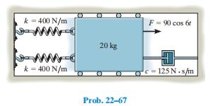
22–67. The 20-kg block is subjected to the action of the harmonic force F = (90 cos 6t) N, where t is in seconds.Write the equation which describes the steady-state motion. k = 400 N/m k = 400 N/m 20 kg Prob. 22-67 F= 90 cos 6 C c-125N.s/m
22–66.A block having a mass of 7 kg is suspended from a spring that has a stiffness k = 600 N>m. If the block is given an upward velocity of 0.6 m>s from its equilibrium position at t = 0, determine its position as a function of time.Assume that positive displacement of the block is downward and
22–65. Determine the magnification factor of the block,spring, and dashpot combination in Prob. 22–64.Data from in Prob 22–64. A 3.5-kg block is suspended from a spring having a stiffness of k = 1250 N>m. The support to which the spring is attached is given simple harmonic motion which can
*22–64. A 3.5-kg block is suspended from a spring having a stiffness of k = 1250 N>m. The support to which the spring is attached is given simple harmonic motion which can be expressed as d = (0.045 sin 2t) m, where t is in seconds. If the damping factor is c>cc = 0.8, determine the phase angle
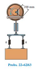
22–63. The spring system is connected to a crosshead that oscillates vertically when the wheel rotates with a constant angular velocity of v = 5 rad>s. If the amplitude of the steady-state vibration is observed to be 400 mm, determine the two possible values of the stiffness k of the springs.
22–62. The spring system is connected to a crosshead that oscillates vertically when the wheel rotates with a constant angular velocity of V. If the amplitude of the steady-state vibration is observed to be 400 mm, and the springs each have a stiffness of k = 2500 N>m, determine the two
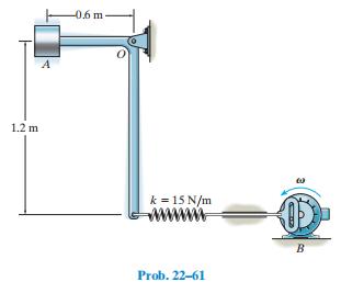
22–61. The small block at A has a mass of 4 kg and is mounted on the bent rod having negligible mass. If the rotor at B causes a harmonic movement dB = (0.1 cos 15t) m, where t is in seconds, determine the steady-state amplitude of vibration of the block. 1.2 m A -0.6 m- k = 15 N/m Prob. 22-61 B
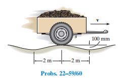
*22–60. Determine the amplitude of vibration of the trailer in Prob. 22–59 if the speed v = 15 km>h. 2m|2m| m- Probs. 22-59/60 100 mm
22–59. The 450-kg trailer is pulled with a constant speed over the surface of a bumpy road, which may be approximated by a cosine curve having an amplitude of 50 mm and wave length of 4 m. If the two springs s which support the trailer each have a stiffness of 800 N>m, determine the speed v
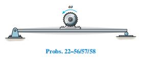
22–58. Determine the angular velocity of the flywheel in Prob. 22–56 which will produce an amplitude of vibration of 6 mm. Probs. 22-56/57/58
22–57. What will be the amplitude of steady-state vibration of the motor in Prob. 22–56 if the angular velocity of the flywheel is 20 rad> s? Probs. 22-56/57/58
*22–56. The electric motor turns an eccentric flywheel which is equivalent to an unbalanced 0.125-kg mass located 250 mm from the axis of rotation. If the static deflection of the beam is 25 mm because of the mass of the motor, determine the angular velocity of the flywheel at which resonance
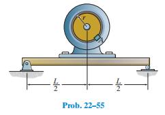
22–55. The motor of mass M is supported by a simply supported beam of negligible mass. If block A of mass m is clipped onto the rotor, which is turning at constant angular velocity of v, determine the amplitude of the steadystate vibration. Hint: When the beam is subjected to a concentrated force
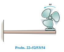
22–54. What will be the amplitude of steady-state vibration of the fan in Prob. 22–52 if the angular velocity of the fan blade is 18 rad>s? Hint: See the first part of Example 22.8. Probs. 22-52/53/54
22–53.In Prob. 22–52, determine the amplitude of steadystate vibration of the fan if its angular velocity is 10 rad>s. Probs. 22-52/53/54
*22–52. The fan has a mass of 25 kg and is fixed to the end of a horizontal beam that has a negligible mass. The fan blade is mounted eccentrically on the shaft such that it is equivalent to an unbalanced 3.5-kg mass located 100 mm from the axis of rotation. If the static deflection of the beam
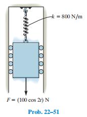
22–51. The 40-kg block is attached to a spring having a stiffness of 800 N>m. A force F = (100 cos 2t) N, where t is in seconds is applied to the block. Determine the maximum speed of the block for the steady-state vibration. k = 800 N/m F= (100 cos 2r) N Prob. 22-51
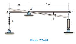
22–50. Find the differential equation for small oscillations in terms of u for the uniform rod of mass m. Also show that if c 1mk >2, then the system remains underdamped. The rod is in a horizontal position when it is in equilibrium. B -2a. Prob. 22-50 C
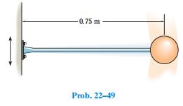
22–49. The light elastic rod supports a 4-kg sphere. When an 18-N vertical force is applied to the sphere, the rod deflects 14 mm. If the wall oscillates with harmonic frequency of 2 Hz and has an amplitude of 15 mm, determine the amplitude of vibration for the sphere. -0.75 m Prob. 22-49
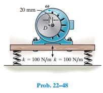
22–48. The electric motor has a mass of 50 kg and is supported by four springs, each spring having a stiffness of 100 N>m. If the motor turns a disk D which is mounted eccentrically, 20 mm from the disk’s center, determine the angular velocity v at which resonance occurs. Assume that the
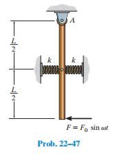
22–47. The uniform rod has a mass of m. If it is acted upon by a periodic force of F = F0 sin vt, determine the amplitude of the steady-state vibration. A L k www.www. F = Fo sin cof Prob. 22-47
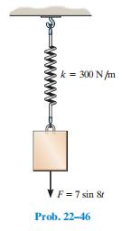
22–46. A 5-kg block is suspended from a spring having a stiffness of 300 N>m. If the block is acted upon by a vertical force F = (7 sin 8t) N, where t is in seconds, determine the equation which describes the motion of the block when it is pulled down 100 mm from the equilibrium position and
22–45. Use a block-and-spring model like that shown in Fig. 22–13a, but suspended from a vertical position and subjected to a periodic support displacement d = d0 sin v0t, determine the equation of motion for the system, and obtain its general solution. Define the displacement y measured from
22–44. A 4-kg block is suspended from a spring that has a stiffness of k = 600 N>m. The block is drawn downward 50 mm from the equilibrium position and released from rest when t = 0. If the support moves with an impressed displacement of d = (10 sin 4t) mm, where t is in seconds, determine the
22–43. The block shown in Fig. 22–15 has a mass of 20 kg,and the spring has a stiffness k = 600 N>m. When the block is displaced and released, two successive amplitudes are measured as x1 = 150 mm and x2 = 87 mm. Determine the coefficient of viscous damping, c.
22–42. A block which has a mass m is suspended from a spring having a stiffness k. If an impressed downward vertical force F = FO acts on the weight, determine the equation which describes the position of the block as a function of time.
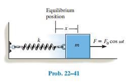
22–41.If the block-and-spring model is subjected to the periodic force F = F0 cos vt, show that the differential equation of motion is x $ + (k >m)x = (F0>m) cos vt, where x is measured from the equilibrium position of the block.What is the general solution of this equation? Equilibrium
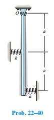
22–40. The slender rod has a mass m and is pinned at its end O. When it is vertical, the springs are unstretched.Determine the natural period of vibration. ww Prob. 22-40
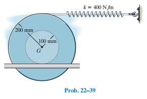
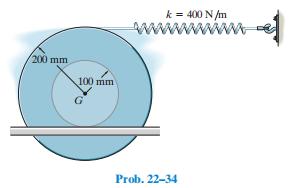
22–39. Determine the differential equation of motion of the 3-kg spool. Assume that it does not slip at the surface of contact as it oscillates. The radius of gyration of the spool about its center of mass is kG = 125 mm. 200 mm 100 mm k = 400 N/m Prob. 22-39
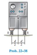
22–38. The machine has a mass m and is uniformly supported by four springs, each having a stiffness k.Determine the natural period of vertical vibration. k d d 2 Prob. 22-38 k
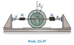
22–37. The gear of mass m has a radius of gyration about its center of mass O of ko. The springs have stiffnesses of k1 and k2, respectively, and both springs are unstretched when the gear is in an equilibrium position. If the gear is given a small angular displacement of u and released,
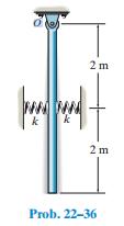
22–36. If the lower end of the 6-kg slender rod is displaced a small amount and released from rest, determine the natural frequency of vibration. Each spring has a stiffness of k = 200 N>m and is unstretched when the rod is hanging vertically. 2 m k 2 m Prob. 22-36
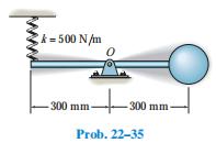
22–35. Determine the natural period of vibration of the 3-kg sphere. Neglect the mass of the rod and the size of the sphere. k=500 N/m -300 mm- 0 -300m -300 mm- Prob. 22-35
22–34. Determine the differential equation of motion of the 3-kg spool. Assume that it does not slip at the surface of contact as it oscillates. The radius of gyration of the spool about its center of mass is kG = 125 mm. 200 mm 100 mm G ww k = 400 N/m Prob. 22-34
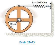
22–33. If the 20-kg wheel is displaced a small amount and released, determine the natural period of vibration. The radius of gyration of the wheel is kG = 0.36 m. The wheel rolls without slipping. 0.5 m k = 500 N/m www Prob. 22-33
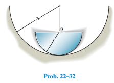
22–32. The semicircular disk has a mass m and radius r,and it rolls without slipping in the semicircular trough.Determine the natural period of vibration of the disk if it is displaced slightly and released. Prob. 22-32
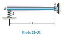
22–31. The uniform rod of mass m is supported by a pin atA and a spring at B. If the end B is given a small downward displacement and released, determine the natural period of vibration. B -1- Prob. 22-31
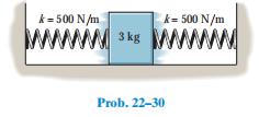
22–30. Determine the differential equation of motion of the 3-kg block when it is displaced slightly and released. The surface is smooth and the springs are originally unstretched. k-500 N/m k-500 N/m www.3kg wwwwww Prob. 22-30
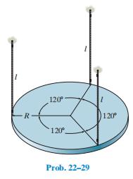
22–29. The plate of mass m is supported by three symmetrically placed cords of length l as shown. If the plate is given a slight rotation about a vertical axis through its center and released, determine the natural period of oscillation. R 120 120 Prob. 22-29 120
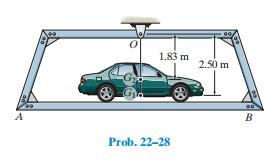
22–28. The platform AB when empty has a mass of 400 kg,center of mass at G1, and natural period of oscillation t1 = 2.38 s. If a car, having a mass of 1.2 Mg and center of mass at G2, is placed on the platform, the natural period of oscillation becomes t2 = 3.16 s. Determine the moment of inertia
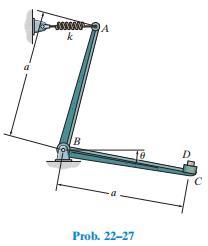
22–27. If a block D of negligible size and of mass m is attached at C, and the bell crank of mass M is given a small angular displacement of u, the natural period of oscillation is t1. When D is removed, the natural period of oscillation is t2. Determine the bell crank’s radius of gyration
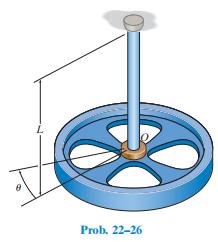
22–26. A flywheel of mass m, which has a radius of gyration about its center of mass of kO, is suspended from a circular shaft that has a torsional resistance of M = Cu. If the flywheel is given a small angular displacement of u and released, determine the natural period of oscillation. L Prob.
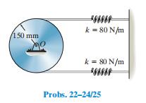
22–25. If the disk in Prob. 22–24 has a mass of 10 kg,determine the natural frequency of vibration. Hint: Assume that the initial stretch in each spring is dO. 150 mm www k = 80 N/m k = 80 N/m www Probs. 22-24/25
22–24. The 10-kg disk is pin connected at its mass center.Determine the natural period of vibration of the disk if the springs have sufficient tension in them to prevent the cord from slipping on the disk as it oscillates. Hint: Assume that the initial stretch in each spring is dO. 150 mm www k =
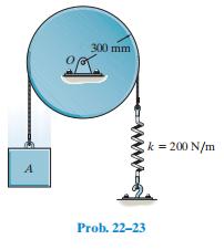
22–23. The 20-kg disk, is pinned at its mass center O and supports the 4-kg block A. If the belt which passes over the disk is not allowed to slip at its contacting surface, determine the natural period of vibration of the system. A 300 mm k = 200 N/m www. Prob. 22-23
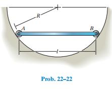
22–22. The bar has a length l and mass m. It is supported at its ends by rollers of negligible mass. If it is given a small displacement and released, determine the natural frequency of vibration. R B Prob. 22-22
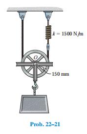
22–21. The 50-kg block is suspended from the 10-kg pulley that has a radius of gyration about its center of mass of 125 mm. If the block is given a small vertical displacement and then released, determine the natural frequency of oscillation. Prob. 22-21 www k-1500 N/m 150 mm
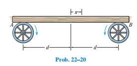
22–20. A uniform board is supported on two wheels which rotate in opposite directions at a constant angular speed. If the coefficient of kinetic friction between the wheels and board is m, determine the frequency of vibration of the board if it is displaced slightly, a distance x from the
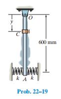
22–19. The slender rod has a mass of 0.2 kg and is supported at O by a pin and at its end A by two springs, each having a stiffness k = 4 N>m. The period of vibration of the rod can be set by fixing the 0.5-kg collar C to the rod at an appropriate location along its length. If the springs are
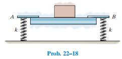
22–18. The uniform beam is supported at its ends by two springs A and B, each having the same stiffness k. When nothing is supported on the beam, it has a period of vertical vibration of 0.83 s. If a 50-kg mass is placed at its center, the period of vertical vibration is 1.52 s. Compute the
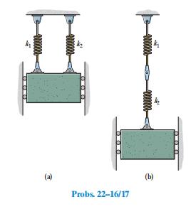
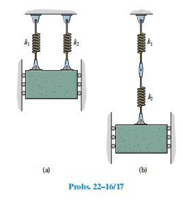
22–17. The 15-kg block is suspended from two springs having different stiffnesses and arrangeda) parallel to each other, andb) as a series. If the natural periods of oscillation of the parallel system and series system are observed to be 0.5 s and 1.5 s, respectively, determine the spring
22–16. A block of mass m is suspended from two springs having a stiffness of k1 and k2, arrangeda) parallel to each other, andb) as a series. Determine the equivalent stiffness of a single spring with the same oscillation characteristics and the period of oscillation for each case. +000000
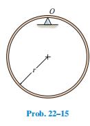
22–15. The thin hoop of mass m is supported by a knifeedge. Determine the natural period of vibration for small amplitudes of swing. Prob. 22-15
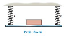
22–14. A platform, having an unknown mass, is supported by four springs, each having the same stiffness k. When nothing is on the platform, the period of vertical vibration is measured as 2.35 s; whereas if a 3-kg block is supported on the platform, the period of vertical vibration is 5.23
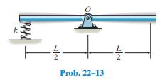
22–13. Determine the natural period of vibration of the uniform bar of mass m when it is displaced downward slightly and released. 22 Prob.22-13
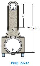
22–12. The connecting rod is supported by a knife edge at A and the period of vibration is measured as tA = 3.38 s.It is then removed and rotated 180° so that it is supported by the knife edge at B. In this case the period of vibration is measured as tB = 3.96 s. Determine the location d of
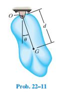
22–11. The body of arbitrary shape has a mass m, mass center at G, and a radius of gyration about G of kG. If it is displaced a slight amount u from its equilibrium position and released, determine the natural period of vibration. G Prob. 22-11
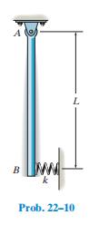
22–10. The uniform rod of mass m is supported by a pin at A and a spring at B. If B is given a small sideward displacement and released, determine the natural period of vibration. B k Prob. 22-10 L
22–9. A 3-kg block is suspended from a spring having a stiffness of k = 200 N>m. If the block is pushed 50 mm upward from its equilibrium position and then released from rest, determine the equation that describes the motion.What are the amplitude and the natural frequency of the vibration?
22–8. A 2-kg block is suspended from a spring having a stiffness of 800 N>m. If the block is given an upward velocity of 2 m>s when it is displaced downward a distance of 150 mm from its equilibrium position, determine the equation which describes the motion. What is the amplitude of the
22–7.A pendulum has a 0.4-m-long cord and is given a tangential velocity of 0.2 m>s toward the vertical from a position u = 0.3 rad. Determine the equation which describes the angular motion.
22–6. An 8-kg block is suspended from a spring having a stiffness k = 80 N>m. If the block is given an upward velocity of 0.4 m>s when it is 90 mm above its equilibrium position, determine the equation which describes the motion and the maximum upward displacement of the block measured from the
22–5. When a 3-kg block is suspended from a spring, the spring is stretched a distance of 60 mm. Determine the natural frequency and the period of vibration for a 0.2-kg block attached to the same spring.
*22–4. When a 2-kg block is suspended from a spring, the spring is stretched a distance of 40 mm. Determine the frequency and the period of vibration for a 0.5-kg block attached to the same spring.
22–3. A spring is stretched 200 mm by a 15-kg block. If the block is displaced 100 mm downward from its equilibrium position and given a downward velocity of 0.75 m>s, determine the equation which describes the motion. What is the phase angle? Assume that positive displacement is downward.
22–2. A spring has a stiffness of 800 N>m. If a 2-kg block is attached to the spring, pushed 50 mm above its equilibrium position, and released from rest, determine the equation that describes the block’s motion. Assume that positive displacement is downward.
22–1. A spring is stretched 175 mm by an 8-kg block. If the block is displaced 100 mm downward from its equilibrium position and given a downward velocity of 1.50 m>s, determine the differential equation which describes the motion. Assume that positive displacement is downward.Also, determine the
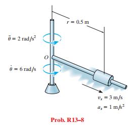
R13–8. The spool, which has a mass of 4 kg, slides along the rotating rod. At the instant shown, the angular rate of rotation of the rod is u # = 6 rad>s and this rotation is increasing at u $ = 2 rad>s 2 . At this same instant, the spool has a velocity of 3 m>s and an acceleration of 1
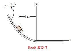
R13–7. The 5-kg suitcase slides down the curved ramp for which the coefficient of kinetic friction is mk = 0.2. If at the instant it reaches point A it has a speed of 2 m>s, determine the normal force on the suitcase and the rate of increase of its speed. y = 1 + E Prob. R13-7 -x
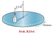
R13–6. The bottle rests at a distance of 1.5 m from the center of the horizontal platform. If the coefficient of static friction between the bottle and the platform is ms = 0.3, determine the maximum speed that the bottle can attain before slipping. Assume the angular motion of the platform is
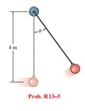
R13–5. The ball has a mass of 30 kg and a speed v = 4 m>s at the instant it is at its lowest point, u = 0 . Determine the tension in the cord and the rate at which the ball’s speed is decreasing at the instant u = 20 . Neglect the size of the ball. 4 m Prob. R13-5
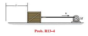
R13–4. If the motor draws in the cable at a rate of v = (0.05s 3>2 ) m>s, where s is in meters, determine the tension developed in the cable when s = 10 m. The crate has a mass of 20 kg, and the coefficient of kinetic friction between the crate and the ground is mk = 0.2. Prob. R13-4 M
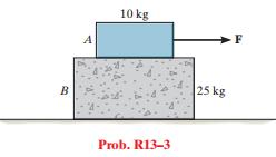
R13–3. Block B rests on a smooth surface. If the coefficients of friction between A and B are ms = 0.4 and mk = 0.3, determine the acceleration of each block ifF = 250 N. B A 10 kg F Prob. R13-3 25 kg
Showing 1 - 100
of 1529
1
2
3
4
5
6
7
8
9
10
11
12
13
14
15
Last
Step by Step Answers