

Question: The rectifier shown in Figure P32.28 converts the alternating emf from an (mathrm{AC}) source to a positive-only potential difference from a to (mathrm{b}). Sketch graphs
The rectifier shown in Figure P32.28 converts the alternating emf from an \(\mathrm{AC}\) source to a positive-only potential difference from a to \(\mathrm{b}\). Sketch graphs showing
\((a)\) the source emf as a function of time and
\((b)\) the potential difference from a to \(\mathrm{b}\) as a function of time.
(c) If diode 1 is blown out and acts as an open circuit, what is the output potential difference from a to \(\mathrm{b}\) ?
(d) What happens to the potential difference from a to \(\mathrm{b}\) if diode 1 operates normally but diode 2 is blown out?
Data from Figure P32.28
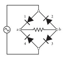
4 1 2 3 b
Step by Step Solution
3.38 Rating (145 Votes )
There are 3 Steps involved in it
Step 1 Normal Operation Positive halfcycle of AC input Diodes 1 and 3 are conducting and current is ... View full answer

Get step-by-step solutions from verified subject matter experts