You are using the logic gate of Figure P32.35 to test some transistors and emf sources. The
Question:
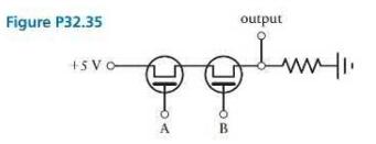
You are using the logic gate of Figure P32.35 to test some transistors and emf sources. The output produced by the logic gate depends on the potential relative to ground at inputs A and B. The only emf sources available to you are \(\mathrm{AC}\) sources, but using one of them to bias either input \(\mathrm{A}\) or input B results in an oscillating input potential. Consider how using an \(\mathrm{AC}\) source affects the potential relative to ground at either A or B. Describe how using an \(A C\) source differs from using a DC source, both in general and in the specific function of this circuit. Could any modifications or additions be made to the circuit so that the way it functions with an \(\mathrm{AC}\) source more closely resembles the way it would function with a DC source? Draw a circuit diagram of any useful modifications.
Data from Figure P32.35
Step by Step Answer:

This question has not been answered yet.
You can Ask your question!