

Question: Use the result of the preceding problem to determine the parity-check matrix for the coder shown in Figure 12.15. Use the parity-check matrix to decode
Figure 12.16
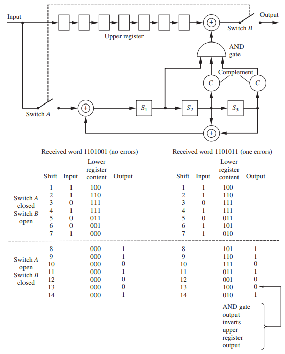
Figure 12.15
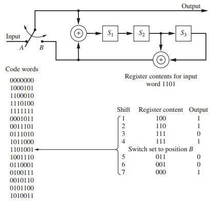
Output -I-I-1-1-I-1-- Input Switch B Upper register AND gate Complement S2 S3 Switch A Received word 1101001 (no errors) Received word 1101011 (one errors) Lower Lower register Shift Input content Output register Shift Input content Output 100 1 100 110 110 Switch A 111 111 closed 11 4 11 Switch B 011 11 open 001 6. 101 000 010 000 8. 101 000 110 Switch A 10 000 10 11 open 1 11 000 11 011 Switch B 12 13 000 12 001 closed 000 13 100 1 14 000 14 010 AND gate output inverts upper register output Output S2 S3 Input Code words Register contents for input word 1101 0000000 1000101 1100010 1110100 1111111 Shift Register content Output 0001011 100 0011101 2 110 1 0111010 3 111 1011000 4 111 1101001+ Switch set to position B 1001110 011 0110001 001 0100111 000 0010110 0101100 1010011
Step by Step Solution
3.37 Rating (166 Votes )
There are 3 Steps involved in it
The paritycheck matrix for the coder in the previous problem is For the received seque... View full answer

Get step-by-step solutions from verified subject matter experts