

Question: Design a feedforwardfeedback control system for the blending system in Example 15.5, for a situation in which an improved sensor is available that has a
Design a feedforward€“feedback control system for the blending system in Example 15.5, for a situation in which an improved sensor is available that has a smaller time delay of 0.1 min. Repeat parts (b), (c), and (d) of Example 15.5. For part (c), approximate GvGpGmwith a frst-order plus time-delay transfer function, and then use a PI controller with ITAE controller tuning for disturbances (see Table 12.4). For the feedforward controller in Eq. 15-34, use α = 0.1. Develop a Simulink diagram for feedforward€“feedback control and generate two graphs similar to those in Fig. 15.13.
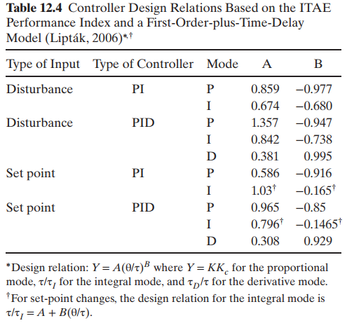
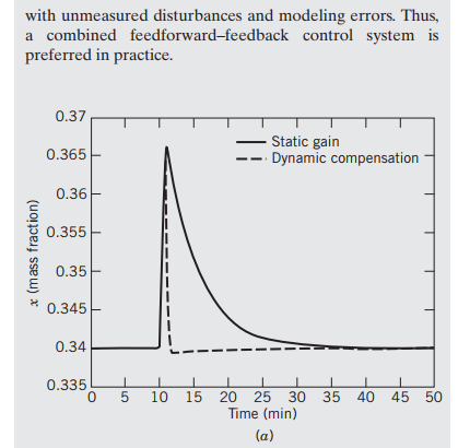
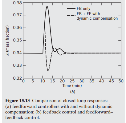
Table 12.4 Controller Design Relations Based on the ITAE Performance Index and a First-Order-plus-Time-Delay Model (Liptk, 2006)* Type of Input Type of Controller Mode A B Disturbance PI 0.859 -0.977 0.674 -0.680 Disturbance PID 1.357 -0.947 0.842 -0.738 D 0.381 0.995 PI Set point 0.586 -0.916 1.03* -0.165* Set point PID 0.965 -0.85 0.796* -0.1465* 0.308 0.929 D *Design relation:Y = A(0/t) where Y = KK for the proportional mode, t/t, for the integral mode, and t,/t for the derivative mode. *For set-point changes, the design relation for the integral mode is t/t, = A + B(0/t). with unmeasured disturbances and modeling errors. Thus, a combined feedforward-feedback control system is preferred in practice. 0.37 Static gain - - Dynamic compensation 0.365 0.36 0.355 0.35 0.345 0.34 0.335 15 20 25 30 35 40 45 50 Time (min) 10 (a) x (mass fraction)
Step by Step Solution
3.35 Rating (161 Votes )
There are 3 Steps involved in it
The block diagram for the feedforwardfeedback control system is shown in Fig 1512 a Not required b Feedforward controlers From example 155 G IP K IP 0... View full answer

Get step-by-step solutions from verified subject matter experts