

Question: Document Review Package for the JMU Sensor for Project X Note: This simulation is fictitious and does not represent nor is intended to represent a
Document Review Package for the JMU Sensor for Project X Note: This simulation is fictitious and does not represent nor is intended to represent a product manufactured by either legacy Goodrich Corporation or United Technologies Corporation. There is no ITAR sensitive data included in this simulation.
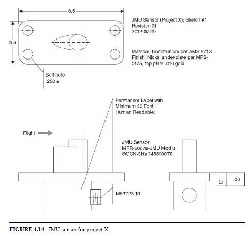
DRAFT Specification for JMU Sensor for Project X for Document Review 1. Packaging shall be a single, ruggedized unit as defined in Fig. 4.14.
2. Sensor unit, consisting of two sensors, shall be designed for mild to harsh environmental conditions and the material shall be 300 series stainless steel.
3. Connector shall be of type D38999/29WJ19PC, wall-mount receptacle, series III, olive-drab finish.
4. Sensor shall fit into a 6-×-6-×-6-in space. Integrated into an airborne vehicle (type TBD). In the interest of lowest manufacturing cost, all interface tolerances shall be such that an as-cast part can meet the tolerance without secondary machining if casting used. If casting is used, unobtanium is the desired material.
5. Temperature range: -200 to +200°C. The connector shall be rated to +100°C 6. Electrical • Current overload: a continuous applied current of (TBD) shall not damage the sensors • Sensor will be supplied with current not to exceed 30 amps • Output voltage shall be 28 VDC 7. Mechanical • Sensor shall withstand vibration testing from (TBD) hertz to (TBD) hertz, at a maximum acceleration of 10 g’s.
• Pressure: each sensor shall withstand a pressure of 20,000 psig using helium gas as the pressuring medium • Visual sensor must be weatherproof • Concept of Operations (CONOPS)
• Sensor shall have a >98% operational readiness capability • Sensor shall support dayight missions up to 12 hours • Sensor shall be a line replaceable unit (LRU)
• Sensor shall be repairable at the shop level to the circuit cardboard (CCB) level • Secondary visual sensor shall provide a color image in standard video interface format 8. Test • Acceptance testing shall consist of demonstrated conformance to the requirements of this specification
3.5 8.5 JMU Sensor (Project X): Sketch #1 Revision 01 2012-07-20 Bolt hole .250 = Material: Unobtainium per AMS 5713 Finish: Nickel under-plate per MPS- 0175, top plate .010 gold Permanent Label with Minimum 36 Font Human Readable: Flight JMU Sensor MFR-60678-JMU Mod o SOCN-3HYT45600078 FIGURE 4.14 JMU sensor for project X. M83723 10 D .00
Step by Step Solution
There are 3 Steps involved in it

Get step-by-step solutions from verified subject matter experts