

Question: For problem in this section, unless otherwise stated, when converting an HLSM to a controller and data path, derive the controller's FSM and only use
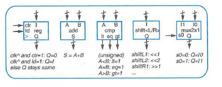
For problem in this section, unless otherwise stated, when converting an HLSM to a controller and data path, derive the controller's FSM and only use data path components from the data path component library of Figure 5.21. Use the RTL design process to create a 4-bit up-counter with input cnt (1 means count up), clear input clr, a terminal count output tc, and a 4-bit output Q indicating, the present count. Only use data path components from Figure 5.21. After deriving the controller's FSM implement the controller as a state register and combinational logic. Requiring a controller and data path pair:
(a) Desired behavior.
(b) HLSM description of desired behavior (LocStr means Local storage),
(c) Data path with potential to implement behavior, but requiring time-varying setting of the data path?s control signal values that should be set in each state to achieve behavior
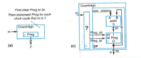
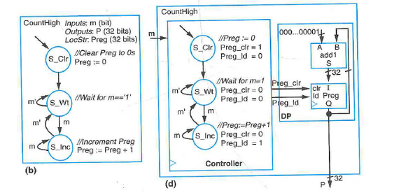
Figure 5.21 A basic data path component library.
First clear Preg to Os Then increment Prog for each clock cycle that m is 1 CountHigh E (a) Preg HAP (c) CountHigh ? 000...000011 Preg_cir Preg_ld DP A B add1 S +32 cir I Id Prog > Q P 32 CountHigh Inputs: m (bit) Outputs: P (32 bits) LocStr. Preg (32 bits) (S_Cir) m' m' m (b) S_Wt m (S_Inc) //Clear Preg to Os Preg := 0 //Wait for m=='1' //increment Preg Preg:= Preg + 1 m CountHigh m' m' mo (d) //Preg := 0 S_Cir) Preg_clr 1 Preg_id = 0 //Wait for m=1 (S_Wt) Preg_clr=0 Preg_id = 0 m //Preg:-Preg+1 (S_Inc) Preg_clr-0 Preg_Id = 1 Controller 000...000011 Preg_cir Preg_ld DP A B add 1 S +32 clr I Id Preg P 32 clr I AB A B 11 10 ld reg add cmp | shift >1 $0=0: Q=10 30-1: Q-11
Step by Step Solution
There are 3 Steps involved in it
To design a 4bit upcounter using the RTL design process lets go through the steps a Desired Behavior A 4bit upcounter with Input Signals cnt Count ena... View full answer

Get step-by-step solutions from verified subject matter experts
Document Format (2 attachments)
6096b697e1242_27128.pdf
180 KBs PDF File
6096b697e1242_27128.docx
120 KBs Word File