

The figure below shows the state transition diagram of a finite state machine (FSM). This diagram shows
Fantastic news! We've Found the answer you've been seeking!
Question:
The figure below shows the state transition diagram of a finite state machine (FSM). This diagram shows the input conditions which initiate the transition. If no input condition is satisfied, then the FSM remains in the same state.
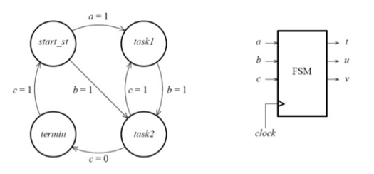
The output are define in the following table.
| State | T | U | V |
| Start_st | 0 | 0 | 0 |
| Task1 | 0 | 1 | 0 |
| Task2 | 1 | 0 | 0 |
| Terminate | 1 | 1 | 1 |
Implement this FSM in VHDL and simulate its behavior with the aid of an appropriate software.
Expert Answer:

Related Book For 

Posted Date:
