

Question: 01) This is a design and simulation problem. Now you have the solutions for the previous HW assignments, you are expected to handle this question
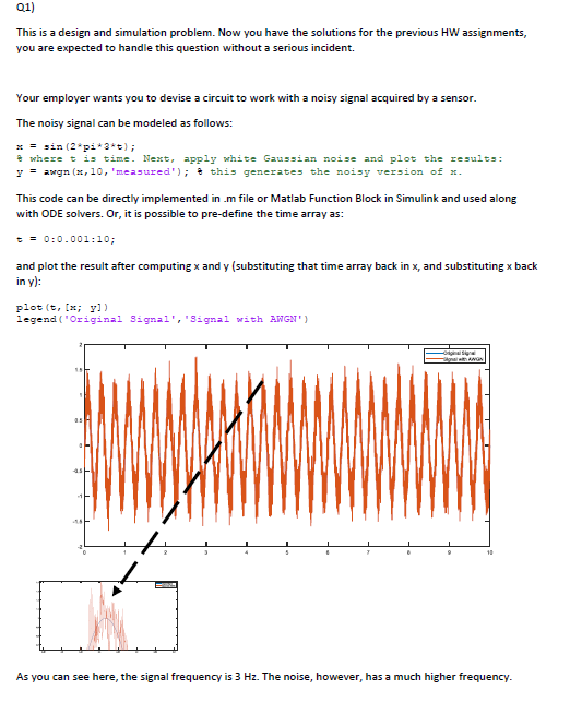
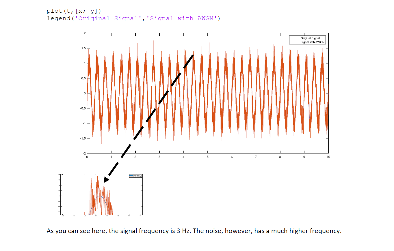
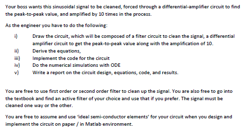
01) This is a design and simulation problem. Now you have the solutions for the previous HW assignments, you are expected to handle this question without a serious incident. Your employer wants you to devise a circuit to work with a noisy signal acquired by a sensor. The noisy signal can be modeled as follows: x = sin (2*pi*3*5); where t is time. Next, apply white Gaussian noise and plot the results: y = awgn (x,10,'measured'); this generates the noisy version of x. This code can be directly implemented in .m file or Matlab Function Block in Simulink and used along with ODE solvers. Or, it is possible to pre-define the time array as: == 0:0.001:10; and plot the result after computing x and y (substituting that time array back in x, and substituting x back in y): plot(t, x; y]) legend (Original Signal', 'Signal with AWGN) ANON 3 As you can see here, the signal frequency is 3 Hz. The noise, however, has a much higher frequency. plot(t, [x; y]) legend ('original Signal', 'Signal with AWGN') Original Signal -Signal with AWGN 1.5 0.5 0 -0.5 -1 -1.5 0 10 As you can see here, the signal frequency is 3 Hz. The noise, however, has a much higher frequency. Your boss wants this sinusoidal signal to be cleaned, forced through a differential-amplifier circuit to find the peak-to-peak value, and amplified by 10 times in the process. As the engineer you have to do the following: i) Draw the circuit, which will be composed of a filter circuit to clean the signal, a differential amplifier circuit to get the peak-to-peak value along with the amplification of 10. ii) Derive the equations, iii) Implement the code for the circuit iv) Do the numerical simulations with ODE v) Write a report on the circuit design, equations, code, and results. You are free to use first order or second order filter to clean up the signal. You are also free to go into the textbook and find an active filter of your choice and use that if you prefer. The signal must be cleaned one way or the other. You are free to assume and use 'ideal semi-conductor elements' for your circuit when you design and implement the circuit on paper / in Matlab environment. 01) This is a design and simulation problem. Now you have the solutions for the previous HW assignments, you are expected to handle this question without a serious incident. Your employer wants you to devise a circuit to work with a noisy signal acquired by a sensor. The noisy signal can be modeled as follows: x = sin (2*pi*3*5); where t is time. Next, apply white Gaussian noise and plot the results: y = awgn (x,10,'measured'); this generates the noisy version of x. This code can be directly implemented in .m file or Matlab Function Block in Simulink and used along with ODE solvers. Or, it is possible to pre-define the time array as: == 0:0.001:10; and plot the result after computing x and y (substituting that time array back in x, and substituting x back in y): plot(t, x; y]) legend (Original Signal', 'Signal with AWGN) ANON 3 As you can see here, the signal frequency is 3 Hz. The noise, however, has a much higher frequency. plot(t, [x; y]) legend ('original Signal', 'Signal with AWGN') Original Signal -Signal with AWGN 1.5 0.5 0 -0.5 -1 -1.5 0 10 As you can see here, the signal frequency is 3 Hz. The noise, however, has a much higher frequency. Your boss wants this sinusoidal signal to be cleaned, forced through a differential-amplifier circuit to find the peak-to-peak value, and amplified by 10 times in the process. As the engineer you have to do the following: i) Draw the circuit, which will be composed of a filter circuit to clean the signal, a differential amplifier circuit to get the peak-to-peak value along with the amplification of 10. ii) Derive the equations, iii) Implement the code for the circuit iv) Do the numerical simulations with ODE v) Write a report on the circuit design, equations, code, and results. You are free to use first order or second order filter to clean up the signal. You are also free to go into the textbook and find an active filter of your choice and use that if you prefer. The signal must be cleaned one way or the other. You are free to assume and use 'ideal semi-conductor elements' for your circuit when you design and implement the circuit on paper / in Matlab environment
Step by Step Solution
There are 3 Steps involved in it

Get step-by-step solutions from verified subject matter experts