

Question: 1 0 . 1 . 1 Clamping device ( B , L 3 , 4 5 min ) The picture shows a clamping device in
Clamping device B Lmin
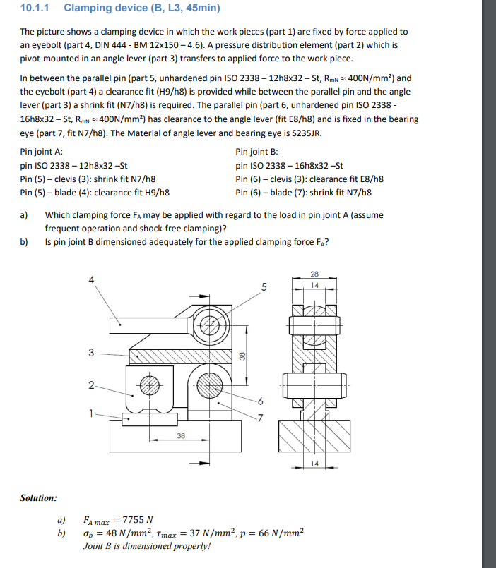
The picture shows a clamping device in which the work pieces part are fixed by force applied to
an eyebolt part DIN BM times A pressure distribution element part which is
pivotmounted in an angle lever part transfers to applied force to the work piece.
In between the parallel pin part unhardened pin ISO ~~ and
the eyebolt part a clearance fit Hh is provided while between the parallel pin and the angle
lever part a shrink fit Nh is required. The parallel pin part unhardened pin ISO
~~ has clearance to the angle lever fit Eh and is fixed in the bearing
eye part fit Nh The Material of angle lever and bearing eye is SJR
Pin joint A:
Pin joint B:
pin ISO St
pin ISO hxSt
Pin clevis : shrink fit Nh
Pin clevis : clearance fit Eh
Pin blade : clearance fit Hh
Pin blade : shrink fit Nh
a Which clamping force may be applied with regard to the load in pin joint assume
frequent operation and shockfree clamping
b Is pin joint dimensioned adequately for the applied clamping force
Solution:
a
b
Joint is dimensioned properly!
Step by Step Solution
There are 3 Steps involved in it
1 Expert Approved Answer
Step: 1 Unlock

Question Has Been Solved by an Expert!
Get step-by-step solutions from verified subject matter experts
Step: 2 Unlock
Step: 3 Unlock