

Question: 1 0 . 1 9 . The positive - sequence reactances for the power system shown in Figure 8 8 are in per unit on
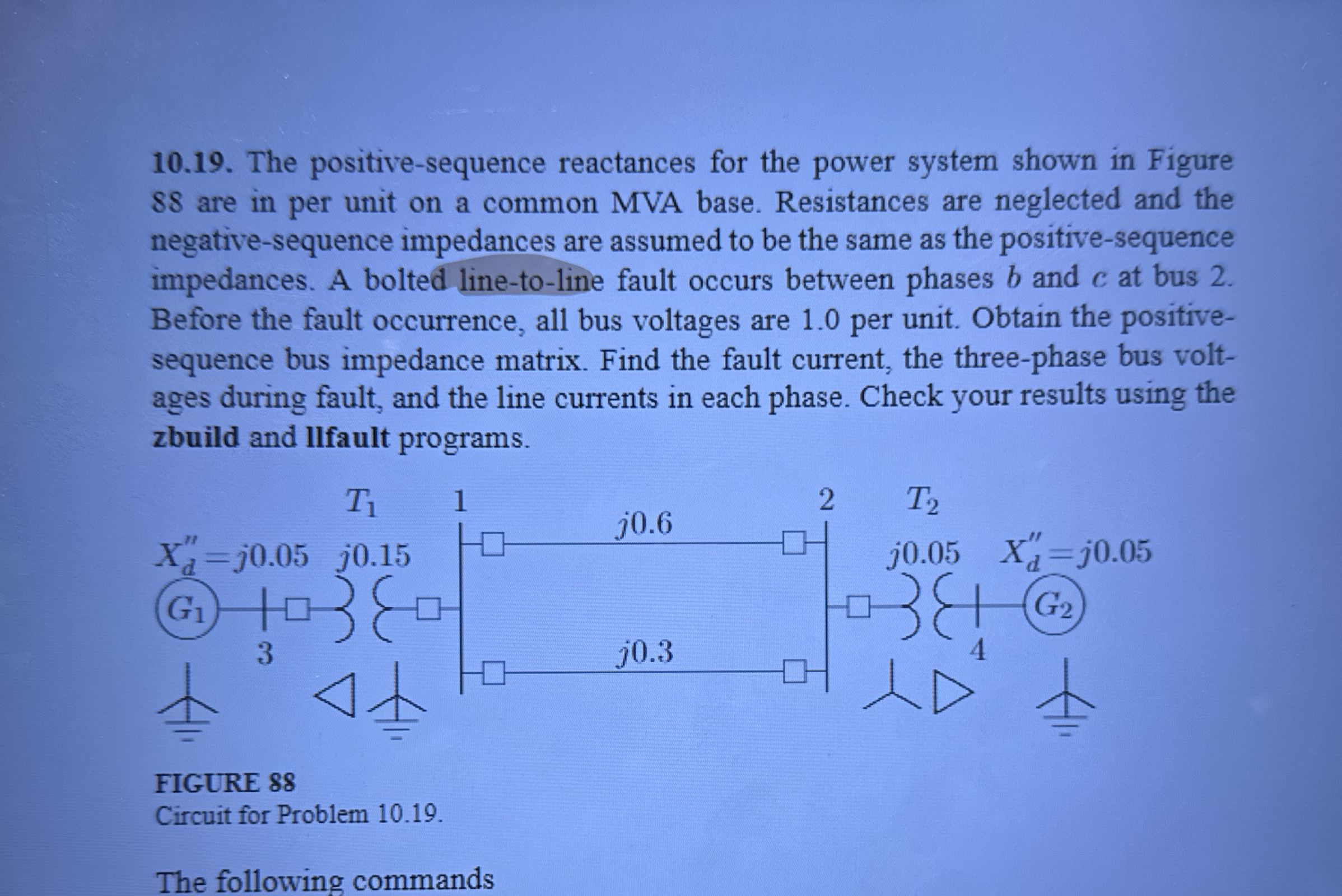
The positivesequence reactances for the power system shown in Figure are in per unit on a common MVA base. Resistances are neglected and the negativesequence impedances are assumed to be the same as the positivesequence impedances. A bolted linetoline fault occurs between phases and at bus Before the fault occurrence, all bus voltages are per unit. Obtain the positivesequence bus impedance matrix. Find the fault current, the threephase bus voltages during fault, and the line currents in each phase. Check your results using the zbuild and llfault programs.
FIGURE
Circuit for Problem
The following command
Find the kind of fault LG
Step by Step Solution
There are 3 Steps involved in it
1 Expert Approved Answer
Step: 1 Unlock

Question Has Been Solved by an Expert!
Get step-by-step solutions from verified subject matter experts
Step: 2 Unlock
Step: 3 Unlock