

Question: Using the bus impedance matrices determined in Problem 9.51, verify the fault currents for the faults given in Problems 9.10, 9.24, 9.25, 9.26, and 9.27.
Using the bus impedance matrices determined in Problem 9.51, verify the fault currents for the faults given in Problems 9.10, 9.24, 9.25, 9.26, and 9.27.
Data From Problem 9.51:-
Compute the \(5 \times 5\) per-unit zero-, positive-, and negative-sequence bus impedance matrices for the power system given in Problem 9.8. Use a base of 100 MVA and \(15 \mathrm{kV}\) in the zone of generator \(\mathrm{G} 2\).
Data From Problem 9.8:-
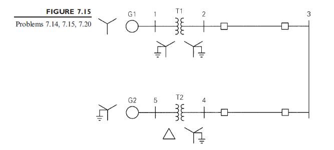
Equipment ratings for the five-bus power system shown in Figure 7.15 are given as follows:
Draw the zero-, positive-, and negative-sequence reactance diagrams using a 100MVA, \(15-\mathrm{kV}\) base in the zone of generator G2. Neglect \(\Delta-\mathrm{Y}\) transformer phase shifts.
Problem 9.10:-
Determine the subtransient fault current in per-unit and in kA during a bolted threephase fault at the fault bus selected in Problem 9.9.
Problem 9.9:-
Faults at bus \(n\) in Problem 9.8 are of interest (the instructor selects \(n=1,2,3,4\), or 5). Determine the Thévenin equivalent of each sequence network as viewed from the fault bus. Prefault voltage is 1.0 per unit. Prefault load currents and \(\Delta-Y\) phase shifts are neglected.
Problem 9.24:-
Determine the subtransient fault current in per-unit and in kA, as well as contributions to the fault current from each line, transformer, and generator connected to the fault bus for a bolted single line-to-ground fault at the fault bus selected in Problem 9.9.
Problem 9.25:-
Repeat Problem 9.24 for a single line-to-ground arcing fault with arc impedance \(Z_{\mathrm{F}}=0.05+j 0\) per unit.
Problem 9.26:-
Repeat Problem 9.24 for a bolted line-to-line fault.
Problem 9.27:-
Repeat Problem 9.24 for a bolted double line-to-ground fault.
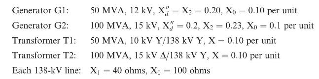
Generator Gl: Generator G2: Transformer T1: Transformer T2: 50 MVA, 12 kV, X = X2 = 0.20, X0 = 0.10 per unit 100 MVA, 15 kV, X = 0.2, X2 = 0.23, X = 0.1 per unit 50 MVA, 10 kV Y/138 kV Y, X = 0.10 per unit 100 MVA, 15 kV A/138 kV Y, X = 0.10 per unit Each 138-kV line: X = 40 ohms, X = 100 ohms ==
Step by Step Solution
3.41 Rating (151 Votes )
There are 3 Steps involved in it

Get step-by-step solutions from verified subject matter experts