

Question: ( 1 0 points ) Ring Counter ( 3 points ) Figure 2 shows the 4 - bit switch - tail ring counter ( known
points Ring Counter
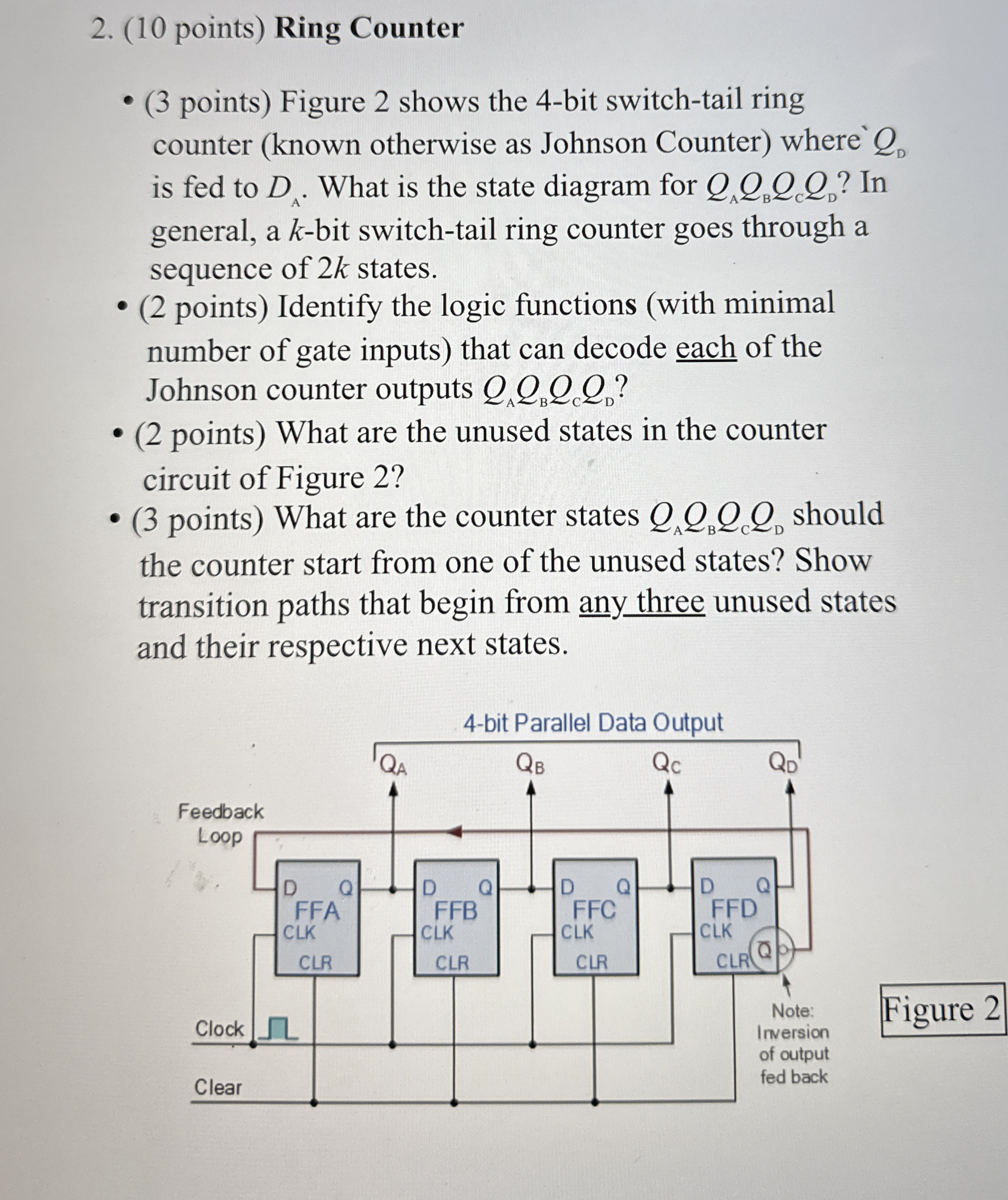
points Figure shows the bit switchtail ring counter known otherwise as Johnson Counter where is fed to What is the state diagram for In general, a bit switchtail ring counter goes through a sequence of states.
points Identify the logic functions with minimal number of gate inputs that can decode each of the Johnson counter outputs
points What are the unused states in the counter circuit of Figure
points What are the counter states should the counter start from one of the unused states? Show transition paths that begin from any three unused states and their respective next states.
Figure
Step by Step Solution
There are 3 Steps involved in it
1 Expert Approved Answer
Step: 1 Unlock

Question Has Been Solved by an Expert!
Get step-by-step solutions from verified subject matter experts
Step: 2 Unlock
Step: 3 Unlock