

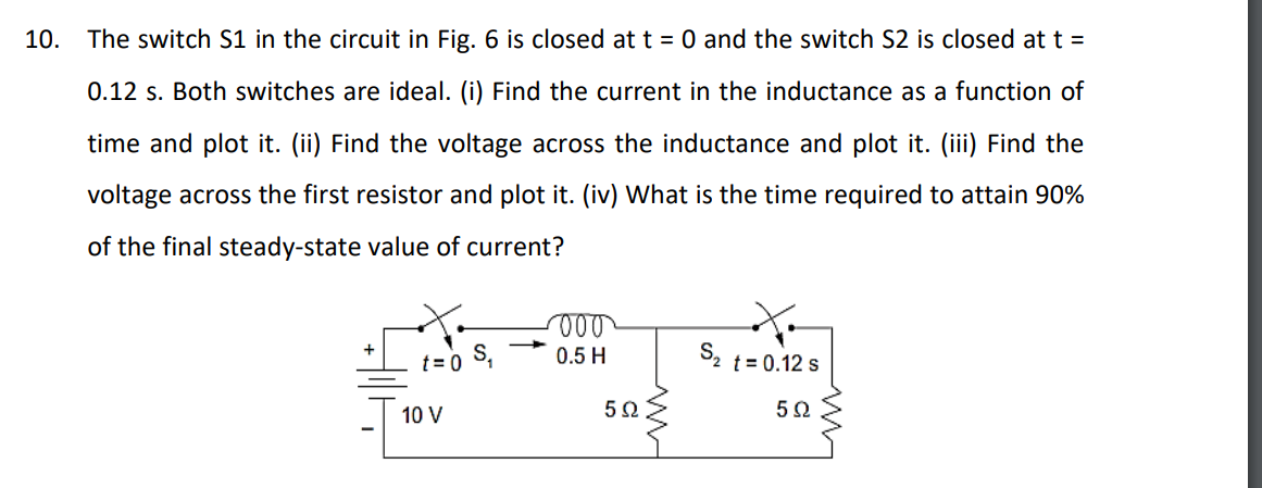
Question: 1 0 . The switch S 1 in the circuit in Fig. 6 is closed at ( t = 0 ) and the
The switch S in the circuit in Fig. is closed at t and the switch S is closed at mathrmt s Both switches are ideal. i Find the current in the inductance as a function of time and plot itii Find the voltage across the inductance and plot itiii Find the voltage across the first resistor and plot itiv What is the time required to attain of the final steadystate value of current?
Step by Step Solution
There are 3 Steps involved in it
1 Expert Approved Answer
Step: 1 Unlock

Question Has Been Solved by an Expert!
Get step-by-step solutions from verified subject matter experts
Step: 2 Unlock
Step: 3 Unlock