

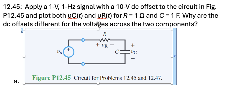
Question: 1 2 . 4 5 : Apply a 1 - V , 1 - Hz signal with a 1 0 - V dc offset to
: Apply a VHz signal with a V dc offset to the circuit in Fig. and plot both vCt and vRt for ROmega and CF
Why are the dc offsets different for the voltages across the two components?
Step by Step Solution
There are 3 Steps involved in it
1 Expert Approved Answer
Step: 1 Unlock

Question Has Been Solved by an Expert!
Get step-by-step solutions from verified subject matter experts
Step: 2 Unlock
Step: 3 Unlock