

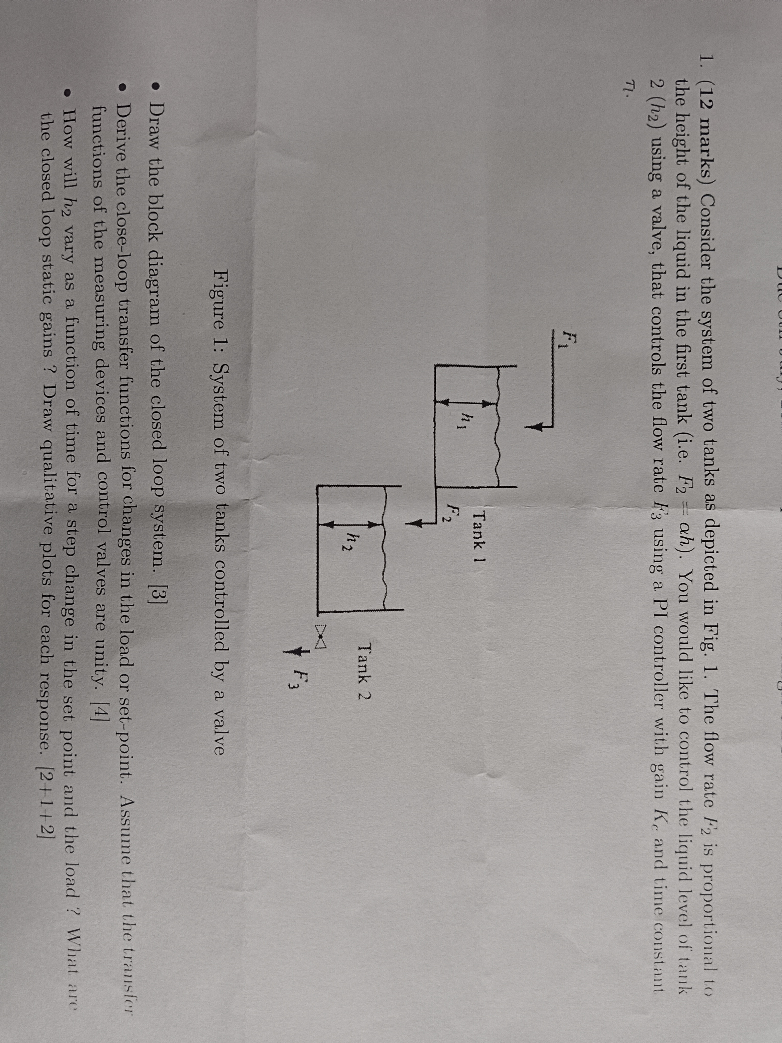
Question: ( 1 2 marks ) Consider the system of two tanks as depicted in Fig. 1 . The flow rate F 2 is proportional to
marks Consider the system of two tanks as depicted in Fig. The flow rate is proportional to
the height of the liquid in the first tank ie You would like to control the liquid level of tank
using a valve, that controls the flow rate using a PI controller with gain and time constant
Figure : System of two tanks controlled by a valve
Draw the block diagram of the closed loop system.
Derive the closeloop transfer functions for changes in the load or setpoint. Assume that the transfer
functions of the measuring devices and control valves are unity.
How will vary as a function of time for a step change in the set point and the load What are
the closed loop static gains Draw qualitative plots for each response.
Step by Step Solution
There are 3 Steps involved in it
1 Expert Approved Answer
Step: 1 Unlock

Question Has Been Solved by an Expert!
Get step-by-step solutions from verified subject matter experts
Step: 2 Unlock
Step: 3 Unlock