

Question: 1) A feedback scheme to control fluid level is shown in the figure below. You need to design and integrate a feedforward control scheme
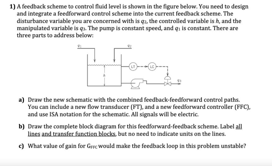
1) A feedback scheme to control fluid level is shown in the figure below. You need to design and integrate a feedforward control scheme into the current feedback scheme. The disturbance variable you are concerned with is q2, the controlled variable is h, and the manipulated variable is q3. The pump is constant speed, and q is constant. There are three parts to address below: 91 LT LC a) Draw the new schematic with the combined feedback-feedforward control paths. You can include a new flow transducer (FT), and a new feedforward controller (FFC), and use ISA notation for the schematic. All signals will be electric. b) Draw the complete block diagram for this feedforward-feedback scheme. Label all lines and transfer function blocks, but no need to indicate units on the lines. c) What value of gain for GFFC would make the feedback loop in this problem unstable? 1) A feedback scheme to control fluid level is shown in the figure below. You need to design and integrate a feedforward control scheme into the current feedback scheme. The disturbance variable you are concerned with is q2, the controlled variable is h, and the manipulated variable is q3. The pump is constant speed, and q is constant. There are three parts to address below: 91 LT LC a) Draw the new schematic with the combined feedback-feedforward control paths. You can include a new flow transducer (FT), and a new feedforward controller (FFC), and use ISA notation for the schematic. All signals will be electric. b) Draw the complete block diagram for this feedforward-feedback scheme. Label all lines and transfer function blocks, but no need to indicate units on the lines. c) What value of gain for GFFC would make the feedback loop in this problem unstable?
Step by Step Solution
There are 3 Steps involved in it

Get step-by-step solutions from verified subject matter experts