

Question: 1. A typical cascade flash separation process is shown in Fig. 6.1 HP Compr LP Compr MP Compr CW CW CW CW To Acid Gas
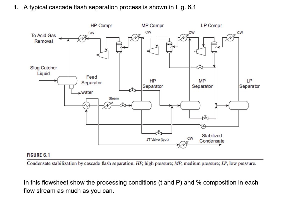
1. A typical cascade flash separation process is shown in Fig. 6.1 HP Compr LP Compr MP Compr CW CW CW CW To Acid Gas Removal Slug Catcher Liquid Feed Separator HP Separator MP Separator LP Separator Water Steam HOR JT Valve (typ.) CW Stabilized Condensate FIGURE 6.1 Condensate stabilization by cascade flash separation. HP, high pressure; MP, medium pressure; LP, low pressure. In this flowsheet show the processing conditions (t and P) and % composition in each flow stream as much as you can. 1. A typical cascade flash separation process is shown in Fig. 6.1 HP Compr LP Compr MP Compr CW CW CW CW To Acid Gas Removal Slug Catcher Liquid Feed Separator HP Separator MP Separator LP Separator Water Steam HOR JT Valve (typ.) CW Stabilized Condensate FIGURE 6.1 Condensate stabilization by cascade flash separation. HP, high pressure; MP, medium pressure; LP, low pressure. In this flowsheet show the processing conditions (t and P) and % composition in each flow stream as much as you can
Step by Step Solution
There are 3 Steps involved in it

Get step-by-step solutions from verified subject matter experts