

Question: 1.) Below is a synchronous sequential circuit with inputs A and B and output Z. 4x16 decoders are used in the circuit. The decoder's selection
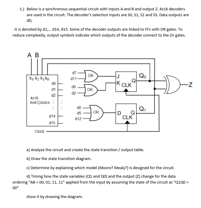
1.) Below is a synchronous sequential circuit with inputs A and B and output Z. 4x16 decoders are used in the circuit. The decoder's selection inputs are SO, S1, S2 and 53. Data outputs are do, It is denoted by d1.... d14, d15. Some of the decoder outputs are linked to FFs with OR gates. To reduce complexity, output symbols indicate which outputs of the decoder connect to the Or gates. AB d7 d11 OR J QO K CLK Z S3 S2 S1S0 do d1 4x16 d2 kod zc : do d2 T OR Q1 do d5 d12 OR d14 d15 Q CLK Clock a) Analyze the circuit and create the state transition / output table. b) Draw the state transition diagram. c) Determine by explaining which model (Moore? Mealy?) is designed for the circuit. d) Timing how the state variables (Q1 and Qo) and the output (Z) change for the data ordering "AB = 00, 01, 11, 11" applied from the input by assuming the state of the circuit as "Q1Q0 = 00" show it by drawing the diagram
Step by Step Solution
There are 3 Steps involved in it

Get step-by-step solutions from verified subject matter experts