

Question: 1. Build the full-wave bridge rectifier circuit as shown below in the LTSpice. 2 Vin D4 D2 D1 D3 a. Add net names to
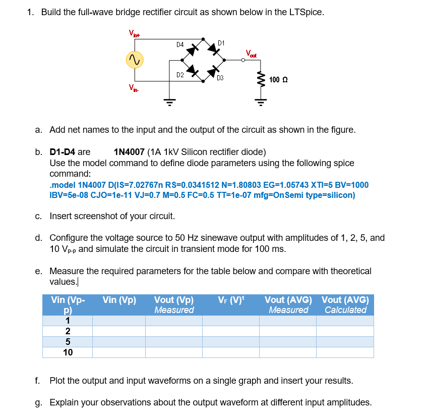
1. Build the full-wave bridge rectifier circuit as shown below in the LTSpice. 2 Vin D4 D2 D1 D3 a. Add net names to the input and the output of the circuit as shown in the figure. b. D1-D4 are 1N4007 (1A 1kV Silicon rectifier diode) Use the model command to define diode parameters using the following spice command: 100 .model 1N4007 D(IS-7.02767n RS=0.0341512 N=1.80803 EG-1.05743 XTI=5 BV=1000 IBV=5e-08 CJO=1e-11 VJ=0.7 M=0.5 FC=0.5 TT=1e-07 mfg-On Semi type=silicon) Vin (Vp- Vin (VP) Vout (Vp) P) Measured 1 2 5 10 c. Insert screenshot of your circuit. d. Configure the voltage source to 50 Hz sinewave output with amplitudes of 1, 2, 5, and 10 Vp-p and simulate the circuit in transient mode for 100 ms. e. Measure the required parameters for the table below and compare with theoretical values. VF (V) Vout (AVG) Vout (AVG) Measured Calculated f. Plot the output and input waveforms on a single graph and insert your results. g. Explain your observations about the output waveform at different input amplitudes.
Step by Step Solution
3.49 Rating (182 Votes )
There are 3 Steps involved in it
a To add net names to the input and output of the circuit you can use the Label component in LTSpice Place the Label component and name it as Vin for the input and Vout for the output b To define the ... View full answer

Get step-by-step solutions from verified subject matter experts